| |
TM10-3930-660-20
18-7.
MLRS ATTACHMENT CONTROL VALVE ASSEMBLY - REPLACE (Cont’ d)
4.
5.
6.
a. Connect eight electrical connectors
(12) as tagged.
b. Tighten eight connector retaining
screws (11) to secure electrical
connectors (12).
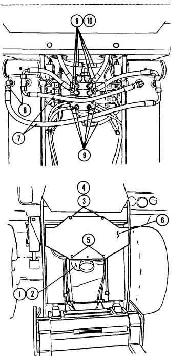
CONNECT HYDRAULIC HOSES TO VALVE AND
FRAME TILT CYLINDERS AS TAGGED.
a. Connect eleven hydraulic hoses (9)
to valve fittings (10) as tagged.
b. Connect two crossover hoses (7) to
carriage tilt cylinder fittings (8)
as tagged.
SECURE VALVE COVER.
a.
b.
c.
Position cover (6) over valve and
align mounting holes.
Apply Loctite 242 to two capscrews
(3) and two nuts (5).
Secure cover (6) with two nuts (5),
two capscrews (3), and two
lockwashers (4).
CONNECT FLOODLIGHT ELECTRICAL LEADS
(1) AND (2) AS TAGGED.
White lead of floodlight connects to
lead 71 of vehicle wiring harness. Black
lead of floodlight connects to lead 02
of vehicle wiring harness.
7. CONNECT NEGATIVE BATTELRY CABLE,
PARA. 8-44.
8. PURGE AIR FROM HYDRAULIC SYSTEM BY
CYCLING EACH MLRS ATTACHMENT FUNCTION
FIVE TIMES, TM10-3930-660-10.
Excessive air in hydraulic system may
temporarily prevent MLRS attachment
functions from operating. Attempt to
operate MLRS attachment functions as
required until each function operates
smoothly and completely.
18-33
|

