| |
TM10-3930-660-20
18-6.
MAIN CONTROL VALVE ASSEMBLY - ADJUST/REPLACE (Cont’d)
4. PURGE AIR FROM HYDRAULIC CIRCUIT.
a. Start engine, TM10-3930-660-10.
b. Cycle boom hoist and extend
functions five times.
C. Shut off engine and check for
leaks, TM10-3930-10.
5. INSTALL TRANSMISSION COVER,
PARA. 16-6.
ADJUSTMENT - MAIN RELIEF VALVE
Adjustment of main control valve
assembly is limited to adjustment of
relief valves.
There are a total of
four relief valves on the main control
valve assembly.
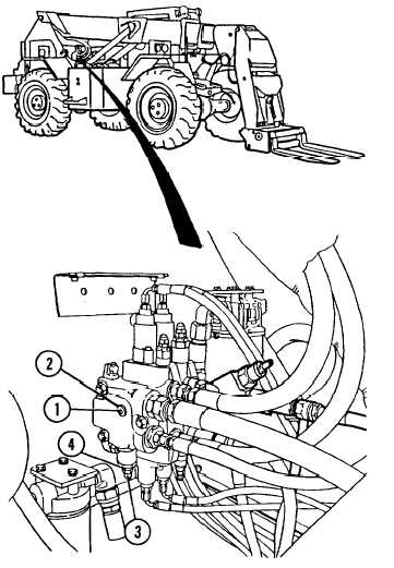
1. CONNECT PRESSURE GAUGE TO VALVE PORT.
a.
b.
c.
d.
Remove main relief valve plug
assembly (l).
Connect O to 5000 psi pressure
gauge to plug assembly port (2).
Start engine.
TM10-3930-660-10.
Operate boom hoist, lower, extend,
or retract function until cylinder
bottoms out and hydraulic oil is
passing over relief valve.
Continue to hold hydraulic lever
in that position so oil passes over
relief valve during relief valve
adjustment.
Engine may be operated at idle or full
throttle when performing tests/
adjustments.
2. READ RELIEF VALVE PRESSURE ON GAUGE.
PRESSURE RANGE IS 2,750 to 2,850
psi.
IF RELIEF VALVE PRESSURE IS NOT
WITHIN SPECIFICATIONS, ADJUST AS
FOLLOWS:
18-20
|