| |
TM10-3930-660-20
8-24. CONSOLB MOUNTED RELAYS - TEST/REPLACE (Cont’d)
TESTING
Testing procedures for all relays
covered in this paragraph are
essentially similar.
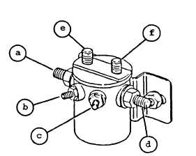
Terminals (a), (b), (c), and (d) are
present on all relays tested in this
section.
Terminals (e) and (f) appear
only on the two blackout headlight
relays.
1.
2.
3.
DISCONNECT ELECTRICAL LEADS
FROM RELAY AS DESCRIBED IN
“REMOVAL” SECTION OF THIS PARAGRAPH.
TEST RELAY FOR PROPER SOLENOID
OPERATION.
a.
b.
Apply 24 volts DC to terminals (b)
and (c).
Listen for “click” when voltage is
applied.
If no “click” is heard,
relay is defective and must be
replaced.
Refer to REMOVAL and
INSTALLATION sections in this
paragraph.
TEST RELAY FOR CONTINUITY.
a.
b.
c.
d.
Apply 24 volts DC to terminals (b)
and (c).
Ohmmeter should indicate
continuity across terminals (a)
and (d).
Ohmmeter should indicate no
continuity across terminals (e)
and (f).
Remove 24 volts DC from terminals
(b) and (c).
4.
5.
e.
f.
9.
Ohmmeter should indicate no
continuity across terminals (a)
and (d).
Ohmmeter should indicate
continuity across terminals (e)
and (f).
Replace relay if continuity
requirements are not met in tests
3a through 3f.
Refer to REMOVAL
and INSTALLATION sections of this
paragraph.
CONNECT ELECTRICAL LEADS TO RELAY AS
DESCRIBED IN “INSTALLATION” SECTION
OF THIS PARAGRAPH.
CONNECT NEGATIVE BATTERY CABLE, PARA.
8-44.
8-64
|

