| |
TM 10-3930-653-14&P
4-3-3. ENGINE LUBRICATION SYSTEM
4-3-3-1. LUBRICATION CIRCUIT
The pressure lubrication of the engine is
accomplished by a spur gear oil pump. This pump draws
the oil through the oil strainer into the pump housing and
then forces it through the full flow type oil filter into the
main oil gallery. Part of the oil is supplied to all the
crankshaft bearings, chain tensioner and timing chain.
Oil supplied to crankshaft bearings is fed to connecting
rod bearings through the drilled passages in the
crankshaft. Oil injected from jet holes on connecting
rods lubricates the cylinder walls and piston pins. The
other part of the oil is brought to the oil gallery in the
cylinder head to provide lubrication of the valve
mechanism and timing chain.
From this gallery, oil holes go directly to all
camshaft bearings.
Oil supplied through the No. 2 and No. 3
camshaft bearings is then fed to the rocker arm, valve
and cam lobe through the oil gallery in the camshaft and
the small channel at the base circle portion of each cam.
4-3-3-2. OIL PUMP
(1) REMOVAL
WARNING
Dry cleaning solvent P-D-680 is toxic
and flammable. Wear protective
goggles and gloves and use only in a
well ventilated area Avoid contact
with skin, eyes, and clothes and don’t
breathe vapors. Do not use near
open flame or excessive heat If you
become dizzy while cleaning with
solvent, get fresh air immediately and
get medical aid. If contact with skin
or clothing is made, flush with water.
If contact with eyes is made, wash
your eyes with water ,and get medical
aid immediately.
(1) Remove distributor.
(4) Disconnect oil tube
(2) Drain engine oil
at pump body.
(3) Remove oil pan.
(5) Remove oil pump
assembly.
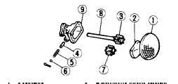
(1) Strainer
(5) Regulator valve spring
(2) Cover
(6) Adjust shim
(3) Drive Gear
(7) Driven gear
(4) Regulator valve
(8) Drive shaft
(9) Body
Fig. 4-103. Component Parts of Oil Pump.
(2) DISASSEMBLY
(1) Remove strainer.
(2) Separate body from cover.
(3) Take out shaft assembly and driven gear.
(4) Draw out cock pin and take out shim, spring and
valve.
(3) INSPECTION
(1) Inspect all components after cleaning them with
P-D-680.
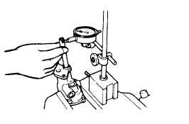
(2) Check clearance between shaft and body bore.
If clearance is in excess of limit, worn part should be
replaced.
Drive shaft dia.
mm (in)
12.958 to 12.976
(0.5105 to 0.5108)
Drive
shaft
to
body
clearance
mm (in)
0.024 to 0.069
(0.0009 to 0.0027)
Limit
mm (in)
0.10 (0.0039)
Fig. 4-104. Inspecting Drive Shaft.
(3) Check clearance between body and gear tooth point.
If clearance exceeds limit, worn part should be replaced.
4-53
|


