| |
TM 10-3930-653-14&P
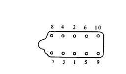
Fig. 4-96. Tightening Sequence of Cylinder Head Bolts.
(5) Install push rods.
Fig. 4-97. Inserting Push Rods.
(17) INSTALLING ROCKER SHAFT ASSEMBLY
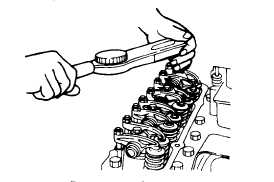
(1) Tighten rocker shaft assembly in same manner as
cylinder head (gradually tightening alternately and evenly
in 3 or 4 stages from center to outside).
Fig. 4-98. Securing Rocker Shaft.
Tightening torque:
Rocker shaft
3.0 to 4.0 kg-m
V
(22 to 29 ft-lb)
’
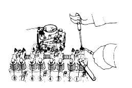
(2) Adjust valve clearance to standard value (at normal
temperature - with engine cool).
Fig. 4-99. Adjusting Valve-Tappet Clearance.
Refer to section 1-3-2 (2)
Model H20 PU240
Intake
valve
clearance
(hot)
0.38 mm (0.015 in)
Exhaust valve clearance
(hot)
0.38 mm (0.015 In)
(3) Install rocker cover.
(18) INSTALLING ENGINE ACCESSORY
Install oil pressure switch.
(19) INSTALLING DISTRIBUTOR
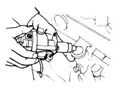
(1) Exercising care so as not to twist O-ring, match
projected part of distributor drive shaft to recess in oil
pump drive gear.
Fig. 4-100. Installing Distributor.
.
(2) Align support and block holes and temporarily secure
with bolts.
4-49
|


