| |
TM 10-3930-653-14&P
(3) Install piston with "F" mark (on piston head) to front.
(4) Set crankshaft pins to top and bottom dead center
position.
(5) Position piston rings so that end gaps are offset
(alternately for adjacent rings) by 180° and so that none
of the end gaps are aligned in piston thrust direction.
(6) Install piston and connecting rod assembly (without
cap) from top.
(7) Install cap on each assembly before Installing the
next piston and connecting rod assembly.
(8) INSTALLING CONNECTING ROD CAPS
Install the connecting rod cap so that the cap and
connecting rod cylinder number markings are aligned (on
the same side).
Turn crankshaft one revolution before installing the
next piston and rod.
Connecting rod caps
5.0 to 6.0 kg-m
(36 to 43 ft-lb)
Fig. 4-87. Tightening Connecting Rod Bearing Caps .
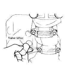
(9) INSTALLING VALVE LIFTERS
Make sure that the valve lifters are installed in proper
direction. Apply oil to the holes in the cylinder block and
lightly press the valve lifters into the holes by hand.
Apply Loc-TiteÒ and install the front plate and packing.
Fig. 4-88. Insert Valve Lifter.
(10) INSTALLING CAMSHAFT
(1) Install the camshaft in place, taking care not to
damage the bearing bushings.
(2) Tighten the bolts attaching the camshaft locating
plate to the cylinder block to the specified torque.
Tightening torque:
Camshaft locating plate to
cylinder block bolts
0.6 to 0.8 kg-m
(4.3 to 5.8 ft-lb)
Temporarily install the camshaft and crank shaft
sprockets in place, and adjust the position of both gears.
using washers. so that they are in line within 0.2 mm
(0.008 in). Align the marks on the gears and timing
chain, and install them to the engine and tighten the
camshaft gear securing nut
Tightening torque:
Camshaft gear securing nut
4.5 to 6.0 kg-m
(33 to 43 ft-lb)
4-46
|


