| |
TM 10-3930-653-14&P
Piston ring end gap:
0.20 to 0.30 mm
(0.0079 to 0.0118 in)
Fig. 4-55. Measuring Piston Ring End Gap
Oversize piston rings
Oversize piston
0.5 (0.020)
ring
1.0 (0.039)
mm (in)
1.5 (0.059)
Standard mm (m)
Limit mm (in)
Top
0.25 to 0.40
1.0 (0.0394)
Piston
(0.0098 to 0.0157)
ring end
Second
0 15 to 0.30
1.0 (0.0394)
gap
(0.0059 to 0.0118)
Oil
0.15 to 0.30
1.0 (00394)
(0.0059 to 0.0118)
CAUTION:
When piston ring only is to be
replaced, without cylinder bore being
corrected, measure gap at bottom of
cylinder where wear is minor.
Ring compression
[Ring end gap
0 51 to 0.84 mm
Service limit
(0.0201 to 0.0331
in)]
1.36 to 1.64
Top ring
kg (lb)
(3 0 to 3.6)
1.05 to 1.35
Second ring
kg (lb)
2.3 to 3.0)
1.32 to 1.68
-O - ring
kg (lb)
(2.9 to 3 7)
(3) PISTON PIN
Check piston-to-piston pin fit for looseness. To
check, warm piston pin in piston with a finger. If piston
pin can be pushed in with some resistance, the fitting is
normal. If loose fitting is detected, replace piston and
piston pin as an assembled unit.
4-2-4-8.
CONNECTING RODS
(1) CORRECTION FOR
BENDING OR TWISTING
(Parallel alignment)
Inspect the thrust surfaces (both ends) and the inner
portion of the large end (crankshaft end) for wear or
damage. and correct or replace. as required. Check
for bending or twisting (parallel alignment) using a
connecting rod alignment tool. If bent or twisted (out of
parallel alignment) beyond the service limit. but within
repair limit, correct with a press. If bent or twisted
beyond repair limit. replace with a new connecting rod.
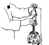
Fig. 4-56. Measuring Parallel Alignment
(Bending and Twisting) of Connecting Rod
Correct to
Service (Bend/twist)
within
limit
Bend/twist
(Parallel align-
(B) 0.07 (0.003)
ment)
0.025 (0.0010)
(T) 0.10 (0.004)
(Per 100 mm)
mm (in)
4 - 34
|


