| |
TM 10-3930-653-1 4&P
4-2-4-6.
CYLINDER BLOCK
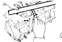
Measuring longitudinal and transverse warp of
cylinder block surface.
Fig. 4-48. Measuring Warp of
Cylinder Block
(1) Remove carbon and other material adherring to
cylinder block surface and Inspect for cracks, scars,
damage, etc. and then measure cylinder head (using a
straight edge and feeler gauge) for both longitudinal and
transverse warp.
Correct to
within
Service limit
Longitudinal
0.05
0.10
direction
(0.0020)
(0.0039)
Cylinder
mm (in)
block
surface
Transverse
direction
0.02
0.04
mm (in)
(0.0008)
(0.0016)
(2) Perform a water leakage test using a hydraulic
pressure of from 4 to 4.5 kg/cm2 (57 to 64 psi).
(1) MEASURING CYLINDER
BORE
Measure the cylinder bore and if excessively worn or
tapered or if scarred. pitted or damaged, or if the piston
rings bind, rebore the cylinder. If only slightly worn or
tapered, merely
correct
the
counter-bore
with
a
counterboring tool.
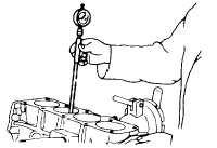
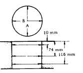
Measure cylinder bore with a cylinder gauge. measuring
in A and B directions at three places from top to bottom.
as shown in the figure, and determine cylinder bore
wear(difference
between
maximum
and
minimum
measurement values).
(difference
between
maximum
and
minimum
measurement values).
Fig. 4-49. Cylinder Bore Measurement
Fig. 4-50. Measuring position of
Cylinder Bore
Correct to
Service
within
(wear) limit
87.20 to
87.25
0.2
Cylinder bore
mm (in)
(3.4331 to
(0.0079)
3.4350)
Cylinder bore out-of-
0.02
-
round limit
mm (in)
(0.0008)
Cylinder bore taper
0.02
-
mm (in)
(0.0008)
Difference in cylinder
0.05
-
bore measurements
mm (in)
4 - 31
|


