| |
TM 10-3930-653-14&P
22. Remove front cover and gasket.
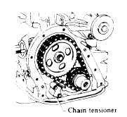
23. Remove chain tensioner.
24. Remove camshaft sprocket. Crankshaft sprocket
and timing chain simultaneously.
Fig. 4-30. Removing Timing Chain
25. Remove crankshaft gear shim, if installed. Shim can
be removed by taking a woodruf key off.
26. Turn engine over.
27. Withdraw valve lifters. Lay out removed valve lifters
in proper order (by cylinder).
28. Remove connecting rod caps.
Pre-set crankshaft pin to top or bottom dead center
(TDC or BDC). Be careful that pistons do not drop. Lay
out bearings according to applicable pistons.
Fig. 4-31. Removing Connecting
Rod Cap
29. Remote flywheel. Straighten bent tongue of lock
pate with a chisel or other appropriate tool.
30. Remove rear plate
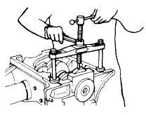
31. Remove rear main bearing cap and rear oil seal.
When removing rear oil seal from knock pin (positioning
pin), be careful not to damage oil seal housing.
Fig. 4-32. Removing Rear Main
Bearing Cap
32. Remove (pull) pistons in direction of cylinder block
fire deck (toward cylinder block). Temporarily secure
cap and connecting rods so that they
are
not
interchanged (mixed) and lay them out in proper order
for each cylinder.
33. Remove two bolts attaching camshaft locating plate.
Then remove camshaft, taking care not to damage metal
surfaces.
34. Remove bearing caps from crankshaft. Remove
seals from both sides of rear bearing cap together with
crankshaft bearing cap.
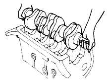
35. Remove crankshaft and bearings.
After bearings are removed. lay them out with
corresponding caps so that the) are not inter-changed
(mixed).
Fig. 4-33. Removing Crankshaft
36. Remove valves and valve springs.
After valves and valve springs are removed, lay them
out by individual cylinders. Be careful not to lose or
damage rubber ring on end of intake valve stem when
removing valves.
4 - 26
|


