| |
TM 10-3930-653-14&P
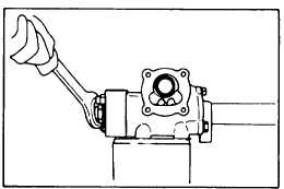
(5) Lightly tighten the valve body with two bottom cover
fitting bolts. Raise the caulked part of the lock nut.
Holding the steering shaft, remove the lock nut.
Fig. 4-431.
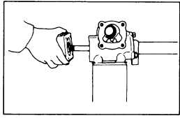
(6) Remove the two bolts which were hand tightened in
the preceding step, and remove the control valve.
Care should be taken to prevent the reaction spring
seat, reaction spring and reaction piston from
popping out.
Fig. 4-432.
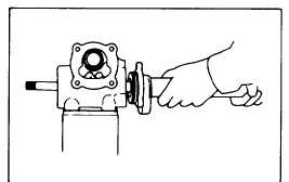
(7) Remove the top cover fitting bolts and remove the
top
cover.
Fig. 4-433.
(8) Remove the worm assembly from the gear box. The
worm assembly must be kept horizontal. Never
disassemble
it.
Fig. 4-434.
4-215
|