| |
TM 10-3930-653-14&P
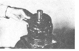
(3) Install piston on shaft, with its flat side pointing toward
drum.
Fig. 4-351.
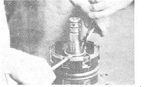
WARNING:
Exercise care when removing snap
rings.
(4)
Install spring, spring retainer and snap ring in
that order.
Fig. 4-352.
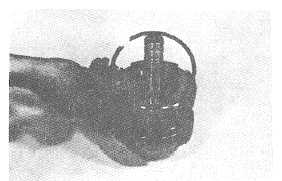
(5)
Install a steel plate then a clutch disc then a steel
plate until there are (4) four of each. Then install
the back plate and finally the snap ring.
Fig. 4-353.
(6)
Install thrust washer and forward gear, matching
with clutch disk inner teeth. (When installing
thrust washer, point chamfered part of its inner
periphery toward spring.
Fig. 4-354.
(7)
Put thrust washer and install bearing. (When
installing thrust washer, its outer periphery
chamfered part should be pointed toward
bearing.) Then install snap ring.
Fig. 4-355.
(8)
Install 3 seal ring.
Fig. 4-356.
4-177
|


