| |
TM 10-3930-653-14&P
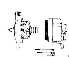
Fig. 4 -177. Separating Front Cover with Rotor from
Rear Cover
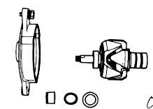
(4) Remove three set screws from bearing retainer, and
separate rotor from front cover.
Fig. 4-178. Removing Rotor
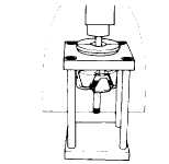
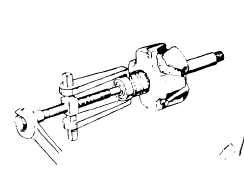
(5) Pull out rear bearing from rotor assembly with a
press or bearing puller.
Fig. 4-179. Pulling Out of Rear Bearing (I)
Fig. 4-180. Pulling Out of Rear Bearing (II)
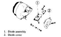
(6) Remove diode cover fixing screw, and remove diode
cover. Disconnect three stator coil lead wires from diode
terminal with a soldering iron.
(’7) Remove "A" terminal nut and diode installation nut,
and remove diode assembly.
Fig. 4-181. Removing Diode Assembly
Note: Use care in handling diode
assembly to prevent undue stress on
it
4-7-5-4. INSPECTION AND REPAIR
Remove alternator from lift truck and apply tester
between lead wire F (white with black tracer) and lead
wire E (black color).
When the resistance is approximately 552, the
condition of brush and field coil is satisfactory. When no
continuity exists in brush or field coil or when resistance
differs remarkably between those parts, disassemble
and inspect.
4-105
|
