| |
TM 10-3930-653-14&P
4-6-3. GOVERNOR
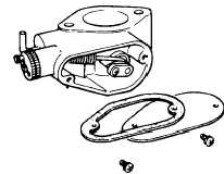
4-6-3-1. DESCRIPTION
Fig. 4-120. Governor (when disassembled)
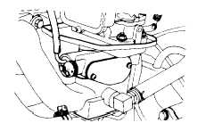
Fig. 4-121. Governor(when mounted)
4-6-3-2. CONSTRUCTION
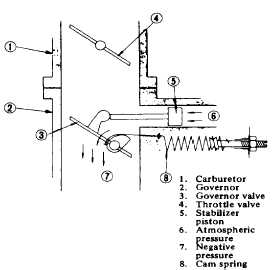
Fig.
4-122.
Construction
Diagram
of
Governor
In the lift truck, the output of the engine is used both
for driving the lift truck and for driving the hydraulic
mechanism to handle cargo. So the load may suddenly
decrease regardless of the operation of the accelerator,
causing a sudden increase of engine speed, which tends
to cause over-running. The governor serves to restrict
the maximum engine speed under no load to prevent
over-running, and at the same time, it acts to hold the
engine output within its rated capacity. It also prevents a
sudden change in engine speed that results from
fluctuations of load.
sudden change in engine speed that results from
fluctuation of load.
This governor is a pneumatic type which is simple in
construction and easy in operation.
In this governor, a governor valve which is
automatically actuated by negative pressure of suction
from the suction passage between the carburetor and
the intake manifold. The amount of mixing air is
regulated, and the engine speed is in turn controlled by
the action of this governor according to the operating
condition of the engine.
The extent of the governor opening is controlled by
the balance of the following two forces:
Force to open governor valve.
Exerted by cam and cam spring.
Force to close governor valve.
Exerted by pressure difference between both
sides of valve plus force of stabilizer piston.
4-6-3-3. OPERATION
(1)
Force to open the valve exerted by the cam and
cam spring.
This force always tends to open the valve, and
exerts certain action even when the valve is fully opened.
When the valve moves towards the closing direction, the
spring tension increases and the working radius of the
cam extends, producing a further increase in the force of
the cam and cam spring which tends to open the valve.
4-73
|


