| |
TM 10-3930-653-14&P
4-5-4-1. REMOVAL AND INSTALLATION
(1) Remove air duct assembly of air cleaner.
(2) Remove fuel pipe.
(3) Remove vacuum control tube.
(4) Remove accelerator and choke wires.
(5) Remove carburetor.
(6) Install in reverse sequence of removal.
4-5-4-2. DISASSEMBLY
To remove nuts and screws, use suitable wrenches
and screw drivers, taking care not to scratch parts.
Disassembled components should be placed in order for
proper reassembly.
(1) CARBURETOR DISASSEMBLY
(1) Remove throttle return spring.
(2) Remove choke wire holder and throttle wire guide.
(3) Remove start connecting rod.
(4) Remove pump connecting rod and pump arm.
(5) Remove throttle shaft set nut, and remove 1st
throttle lever, 1st throttle arm and starting throttle lever.
(6) Remove air horn.
(7) Remove body from flange set.
(2) BODY
(1) Remove the four screws holding the float cover.
(2) Remove the float cover and gasket.
(3) Remove the float pin collar, float and float valve
assembly.
(4) Release union bolt and take off gasket, fuel
connector assembly, strainer and fuel connector gasket.
(5) Loosen float valve seat and take it off together with
float valve seat gasket.
(6) Remove main air bleed and take out small venturi.
(7) Remove slow jet and slow air bleed.
(8) Remove pump outlet valve plug and pump nozzle
plug.
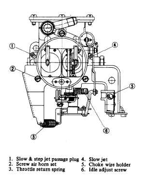
Fig. 4-118. Carburetor.
(9) Take out weight and ball of pump outlet valve.
When installing, place ball on inner side.
(10) Take out pump strainer clip at pump cylinder base
and take out strainer and ball of inlet valve.
(11) Take off main passage plug and remove main
passage plug and remove main jet, respectively.
(2) AIR HORN
(1) Remove choke valve connecting rod.
(2) Releasing choke valve set screw, remove choke
valve.
4-68
|