 |
|||
|
|
|||
|
|
|||
| ||||||||||
|
|
 TM 10-3930-644-14&P
HOSE REEL
A. INSTALLATION
CAUTION
Hold onto reel and allow It to turn
1. The hose reel must be installed in such a
slowly until spring tension is
manner as to eliminate any interference when
relieved.
mast is tilted all the way back. Reel should be
mounted so that inner flange is as close as
2. Remove four nuts and lockwashers holding
possible to mast channel (maximum 1/4"
spring can in place. With one hand, pull spring
clearance) so as to keep reel within the overall
can slowly away from flange, slide other hand
width of the truck.
between spring can and the flange to prevent
spring from Jumping out of can. Slide can from
2. The junction block must be installed on the
shaft and place it over a pan to allow any excess
center line of the middle divider of the hose reel.
oil to drain.
This permits hoses to wind properly.
3. Remove snap ring and slide flange assembly
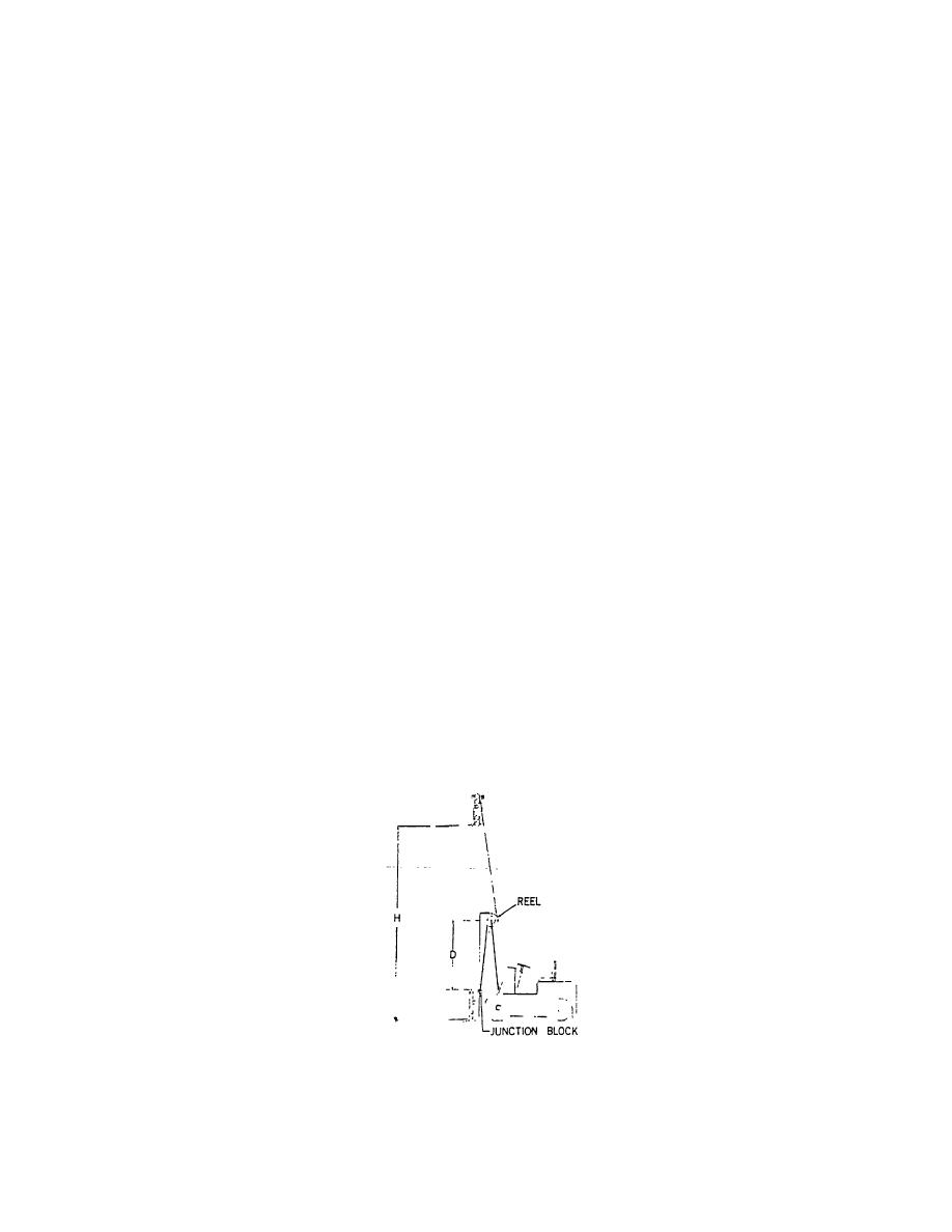
3. Install the hoses to the hose reel and wrap
from shaft. O-rings and back-up rings are now
hoses around reel. Raise the lift truck carriage
exposed for replacement. O-rings and back-up
until the junction block is even with the hose
rings must be replaced in a set.
reel. Turn hose reel three complete turns by
pulling on hose. This provides proper tension on
4. Thoroughly lubricate o-rings and back-up rings
hose. Hold hose securely and wrap hose back
with hydraulic oil before installing hub and flange
around reel and connect to junction block.
assembly. When installing the flange assembly
back onto the shaft, use a rotary motion while
4. Raise and lower lift truck carriage and check reel
pushing flange assembly onto shaft. This will
for proper winding of hose. It may be necessary
reduce chance of nicking o-ring.
to twist hose slightly to get hose to wind
properly.
5. Replace snap ring on shaft.
B. SERVICE
6. If spring assembly is dry, or needs additional
lubrication, apply small amount of Molygrease to
Hose reel can be serviced either on or off the lift truck.
spring.
1. Raise carriage until junction block is even with
7. Slide spring can onto shaft. B. sure spring
hose reel. Disconnect hose.
enters slot on radiused side. Secure spring can
in place with four nuts and lockwashers.
Figure 1. Hose Length Calculation
3-204
|
|
Privacy Statement - Press Release - Copyright Information. - Contact Us |