 |
|||
|
|
|||
|
Page Title:
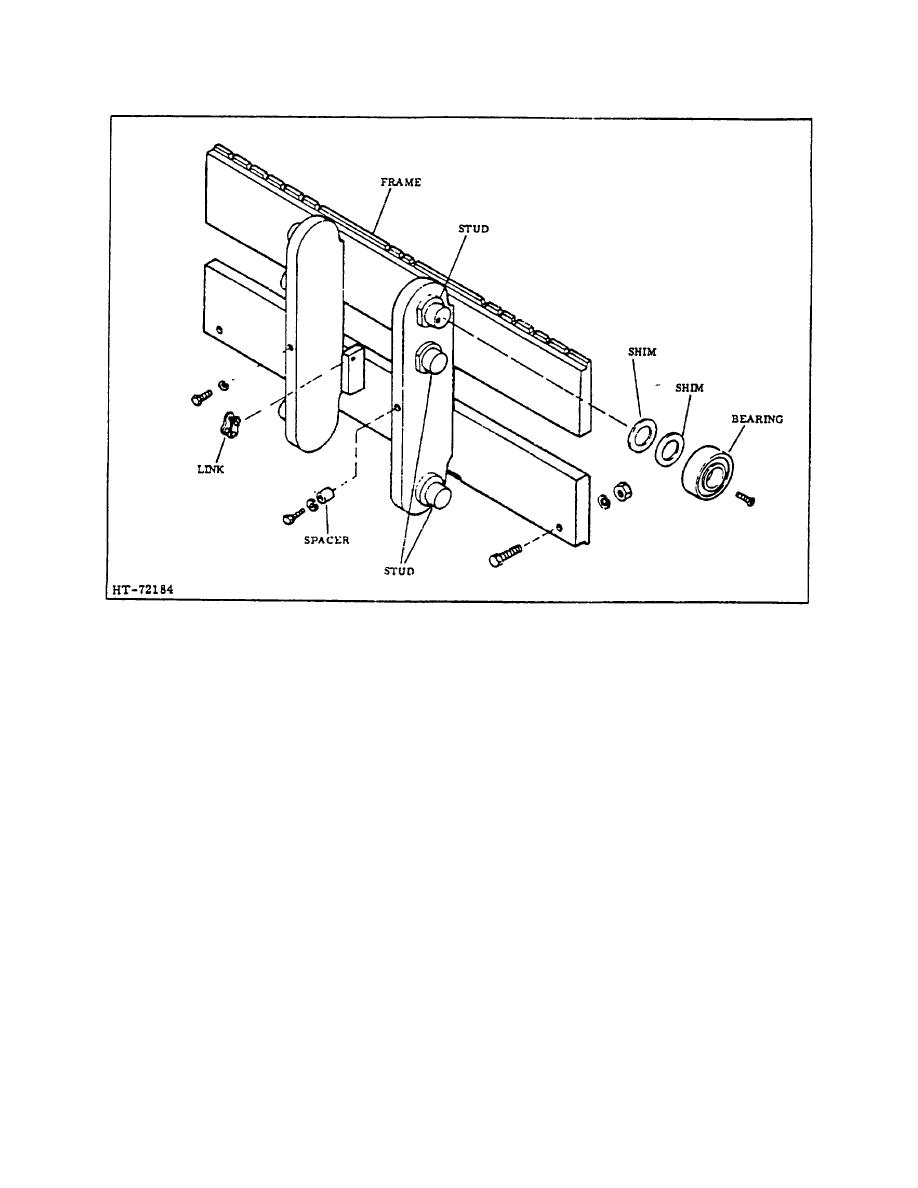
Figure 4. Tri-Max and High Free Lift Carriage Assembly |
|
||
| ||||||||||
|
|
 TM 10-3930-644-14&P
Figure 4. Tri-Max and High Free Lift Carriage Assembly
C. TRI-FREE LIFT CARRIAGE SERVICE
D.
TRI -MAX AND HIGH FREE LIFT CARRIAGE
INSTALLATION
1. Disassemble all the roller assemblies.
1. Block the inner mast assembly to allow
2. Do not intermix parts from the roller assemblies.
approximately 24" clearance between the mast
and floor.
3. Clean and inspect all parts for excessive
damage or wear. Replace as required.
2. Using a suitable hoist, lift carriage assembly into
its relative mounting position, then carefully
4. Reassemble the roller assemblies; Install any
guide It into the bottom of the Inner mast
other parts removed.
channel.
5. To adjust for any carriage side play after
3. Keeping tension off of carriage, install lift chains
installation, run the carriage up and down to
at carriage anchors and secure with anchor pins.
determine the narrowest point on the mast.
4. Install the spacer and capscrews at carriage
6. After determining the narrowest point, loosen the
roller supports.
four (4) locking screws, then tighten same
screws until the side play is eliminated at the
5. Install carriage forks.
narrowest point on the mast.
6. Remove mast support blocks.
3-196
|
|
Privacy Statement - Press Release - Copyright Information. - Contact Us |
