 |
|||
|
|
|||
|
Page Title:
BEARING ADJUSTMENT (TRI-MAX MAST) |
|
||
| ||||||||||
|
|
 TM 10-3930-644-14&P
5. After the adjustment is completed, tighten the
locknuts securely and make certain adjustments
were not turned.
G. BEARING ADJUSTMENT (TRI-MAX MAST)
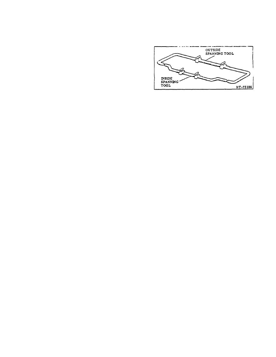
1. Cuter Mast Assembly. Use an adjustable inside
spanning tool and check the rear inside of the
outer mast upright to find narrowest distance
between uprights. Lock tool in this position. Set
an adjustable outside spanning tool to match
Figure 2. Setting Outside Spanning Tool
inside spanning tool. Lock tool in this position.
equally as possible under both bearings to
2. Intermediate Mast Assembly. Install bearings on
provide maximum .015 inch clearance.
studs located at bottom of intermediate mast
assembly. Use an outside spanning tool as set
4. Inner and Intermediate Mast Bearings. Perform
in Step I above and span bearings at maximum
Steps 2 and 3 to adjust upper bearings on inside
camber point. Shim bearings, if required, to
of intermediate mast and lower bearings on
obtain maximum .015 inch clearance between
inner mast.
bearings and outside spanning tool. Divide
shims as equally as possible between bearings.
5. Carriage Assembly Bearings.
Use inside
Shims available in 0.015 and 0.
040 inch
spanning tool and check inside of web of inner
thicknesses.
mast assembly and determine narrowest point.
Set outside spanning tool to match Inside
NOTE
spanning tool. Lock tool in position. Install
If odd shim is required, place odd
bearings on roller studs on carriage. Span
shims on same side of all mast
bearings on carnage assembly at the maximum
sections and carriage so mast will be
camber point with outside spanning tool. Span
in balance.
all three sets of bearings. Shim bearings to
produce maximum .015 inch clearance with
3. Cuter Mast Assembly Top Bearing. Use outside
spanning tool. To check bearing alignment,
spanning tool and find widest point in outside
place a straightedge against stud centerline to
width of web on intermediate mast assembly.
all three bearings on both sides of carriage
Install bearings on studs at top inside of outer
assembly.
No visible gap should be seen
mast. Use inside spanning tool to span bearings
between bearings and the straightedge.
at maximum camber point. Check clearance
between outer and inner spanning tools.
6. After assembly raise and lower the mast and
Measure clearance accurately and install shims
carriage several times to check for free
to provide proper clearance. Install shims as
movement throughout the entire range of travel
TOPIC 2. LIFT CYLINDERS
A. DESCRIPTION
A flow regulator, which is located at the oil inlet port of
the lift cylinder(s), controls the flow of hydraulic nil so
Various renderings of the lift cylinder mechanism are
that the load lowers at a controlled rate of speed from
available depending on the type of mast assembly used
the raised position.
on the lift truck. All lift cylinders operate by the same
hydraulic principles regardless of their multiplicity or
B. SERVICE
arrangement.
After each 50 hours of operation, inspect the mast lift
cylinder(s). cylinder hoses and fittings for evidence of
The hydraulic oil enters the lift cylinder(s) at, or near.
leaks and repair as necessary.
the base of the cylinder(s) causing the plunger(s) to
extend.
The following procedures are recommended for the
proper removal of the respective lift cylinders noted:
3-192
|
|
Privacy Statement - Press Release - Copyright Information. - Contact Us |
