 |
|||
|
|
|||
|
|
|||
| ||||||||||
|
|
 TM 10-3930-644-14&P
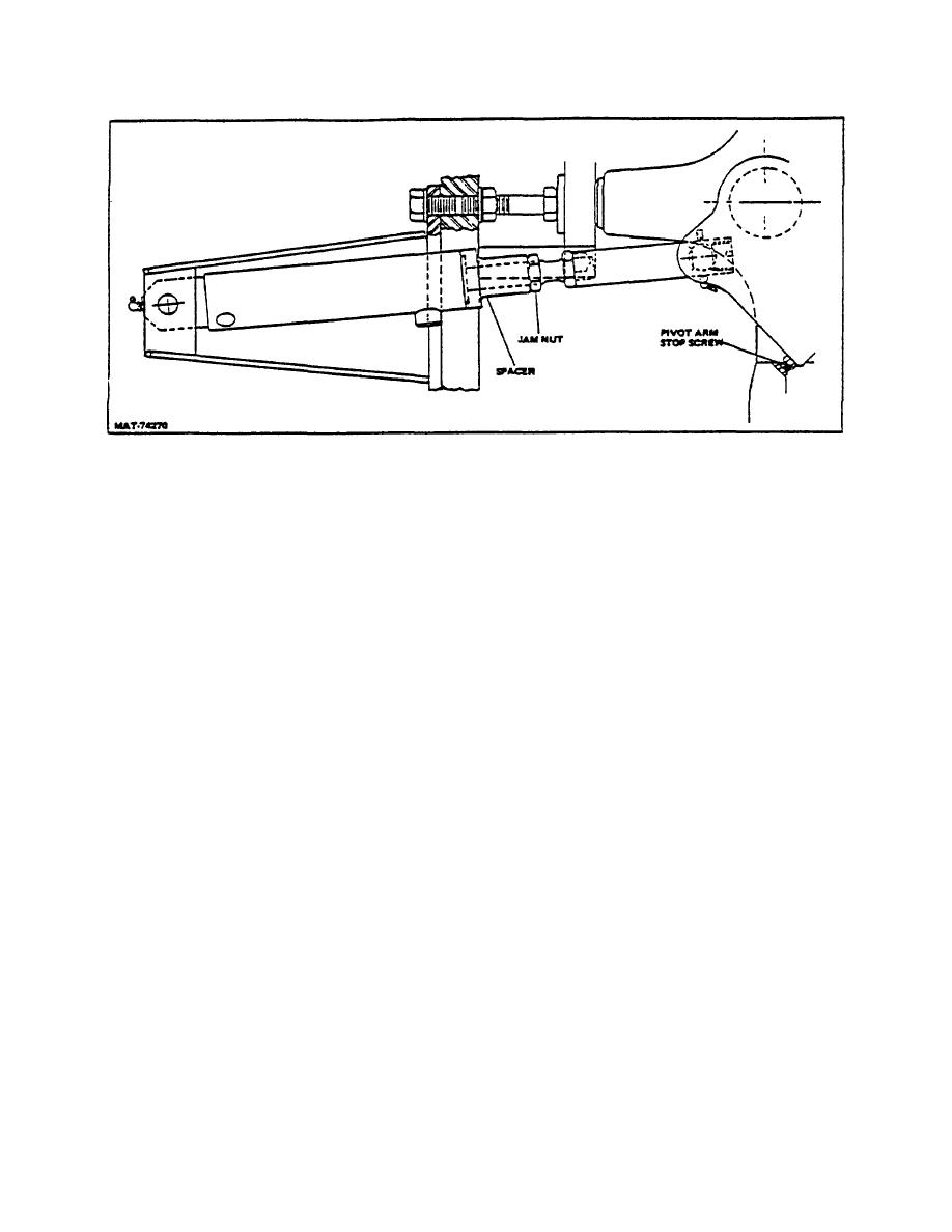
Figure 34. Cylinder Rod Adjustment for Left-Hand Turn
TOPIC 5. TIE RODS
A. REMOVAL
C. INSTALLATION
1. Remove
cotter
pins,
adjusting
plugs
Assemble the nut, ball socket, cup, seats, spring, and
(Fig. 3, 4, and 5), ball seats, and springs from
plug to tie rods. Position the tie rods on the pivot arm
the tie rods, and separate the tie rods from the
and tighten plug until seats firmly grasp ball stud on the
pivot arm.
pivot arm. Install ball socket on spindle and secure with
nut and cotter pin.
2. Remove cotter pin and nut from ball socket, and
remove the tie rods from the spindles. Loosen
D. TIE ROD ADJUSTMENT
the nut on the ball socket, and remove the ball
socket and nut from the tie rod tubes.
Set the steer wheels straight ahead, parallel with the
frame. If wheels are not parallel, adjust the tie rods to
B. CLEANING AND INSPECTION
obtain this position. Zero degrees (0) toe-in must be
maintained at all times. To adjust tie rod, remove cotter
1. Clean all parts with mineral spirits or other
pin and retaining nut that secures tie rod ball socket to
suitable solvent, and dry with compressed air.
steer wheel spindle. Remove ball socket from spindle
and loosen nut that secures ball socket to tie rod. With
2. Inspect all parts for cracks, breaks, bends, other
the steer wheel parallel to the frame, turn ball socket IN
damage, and wear. Repair or replace parts as
or OUT until proper adjustment is obtained. Position ball
indicated by their condition.
socket in steer wheel spindle, install retaining nut
securely, and install cotter pin; then tighten ball socket
3. Lubricate all parts except the ball sockets with
nut securely.
an SAE 10 or 20 oil. Pack the tie rod ball
sockets with high quality chassis lube.
3-175
|
|
Privacy Statement - Press Release - Copyright Information. - Contact Us |