 |
|||
|
|
|||
|
Page Title:
Brake Shoes - Self-Adjusting |
|
||
| ||||||||||
|
|
 TM 10-3930-644-14&P
hydraulic brake system requires a "solid column of fluid"
the two slide assemblies of the self adjuster is
and the fluid should possess essential protective
great enough to prevent the brake shoe springs
properties which safeguard the system.
from fully retracting the self adjuster, but not
great enough to prevent the hydraulic pressure
from expanding it. The self-adjuster assembly is
CAUTION
mounted to the brake shoes with roll pins. The
Because of the importance of the
roll pin holes in the brake shoes are 1/32"
fluid used in the brake hydraulic
oversize to provide proper working clearance
system, use only premium quality,
between the brake shoe lining and drum.
heavy duty brake fluid with an
extreme
heat-cold
range
that
conforms to SAE specification 70-R1.
CAUTION
Exercise care when self-adjuster is
1. Operation of Wheel Cylinders and Brake Shoes
handled or installed. Do not bend the
tangs of the slide assemblies in any
Hydraulic fluid entering the wheel cylinders from
way because the holes for the roll
the master cylinder forces pistons to move
pins must be parallel with each other.
individually and in opposed directions. This
If the holes are not parallel, the roll
piston travel expands the brake shoes. As the
pins will tie at a slight angle through
pressure increases, the piston cup lips are
the mounting holes in the brake
forced more tightly against the cylinder wall,
shoes. Improper alignment of the roll
effecting a positive fluid seal, neglecting minor
pins could lead to improper brake
friction losses. The controlled actuating force is
shoe retraction due to lack of proper
equal to and varies with the hydraulic pressure
roll pin clearance in the brake shoe
exerted against each square inch of the piston
holes.
This in turn could create
face.
brake shoe drag on the drum.
The pistons are returned to an "off" position by
In order for the self-adjusting brakes to operate
the force of the brake shoe retracting springs.
properly, the self adjuster assembly must be
The piston cup lips are pressed against the
properly torqued. If it becomes necessary to
cylinder walls by natural resiliency and system
remove and disassemble the self adjuster in the
residual pressure to seal against fluid or air
field, then it must be carefully reassembled and
leaks.
The hydraulic pistons of the wheel
installed as outlined In the installation section.
cylinders follow the brake shoes as they expand
into the drums.
B. REMOVAL
2. Brake Shoes - Self-Adjusting
Before removing drive wheels.
drive truck (loaded
preferred) and make an eat, rolling stop. Any pulsation
The brake shoes are self-adjusting through the
or vibration on the foot pedal indicates out-of-round
use of a friction operated self-adjuster in each
drums. In order to perform any service on components
drive wheel. The friction between
of the drive wheel brakes, disassemble according to the
following instructions.
1. Remove drive wheel assembly and components
to expose the wheel cylinders and brake shoes
(Figure 3).
(Refer to DRIVE WHEEL
REMOVAL, MAINTENANCE MANUAL.)
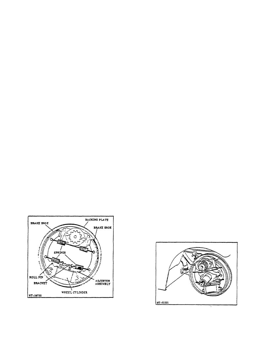
Figure 2. Self-Adjusting Brakes (Typical)
Figure 3. Dust Shield Removed
3-148
|
|
Privacy Statement - Press Release - Copyright Information. - Contact Us |