 |
|||
|
|
|||
|
|
|||
| ||||||||||
|
|
 TM 10-3930-644-14 & P
d. Failure to operate with no current draw
indicates:
(1) Open field circuit.
This can be
checked after disassembly by
inspecting internal connections and
tracing circuit with a test lamp.
(2) Open armature coils. Inspect the
commutator for badly burned bars
after disassembly.
(3) Broken
brush
springs,
worn
brushes, high insulation between
the commutator bars or other
causes which would prevent good
contact between the brushes and
commutator.
e. Low no-load speed and low current draw
indicates:
(1) High internal resistance due to poor
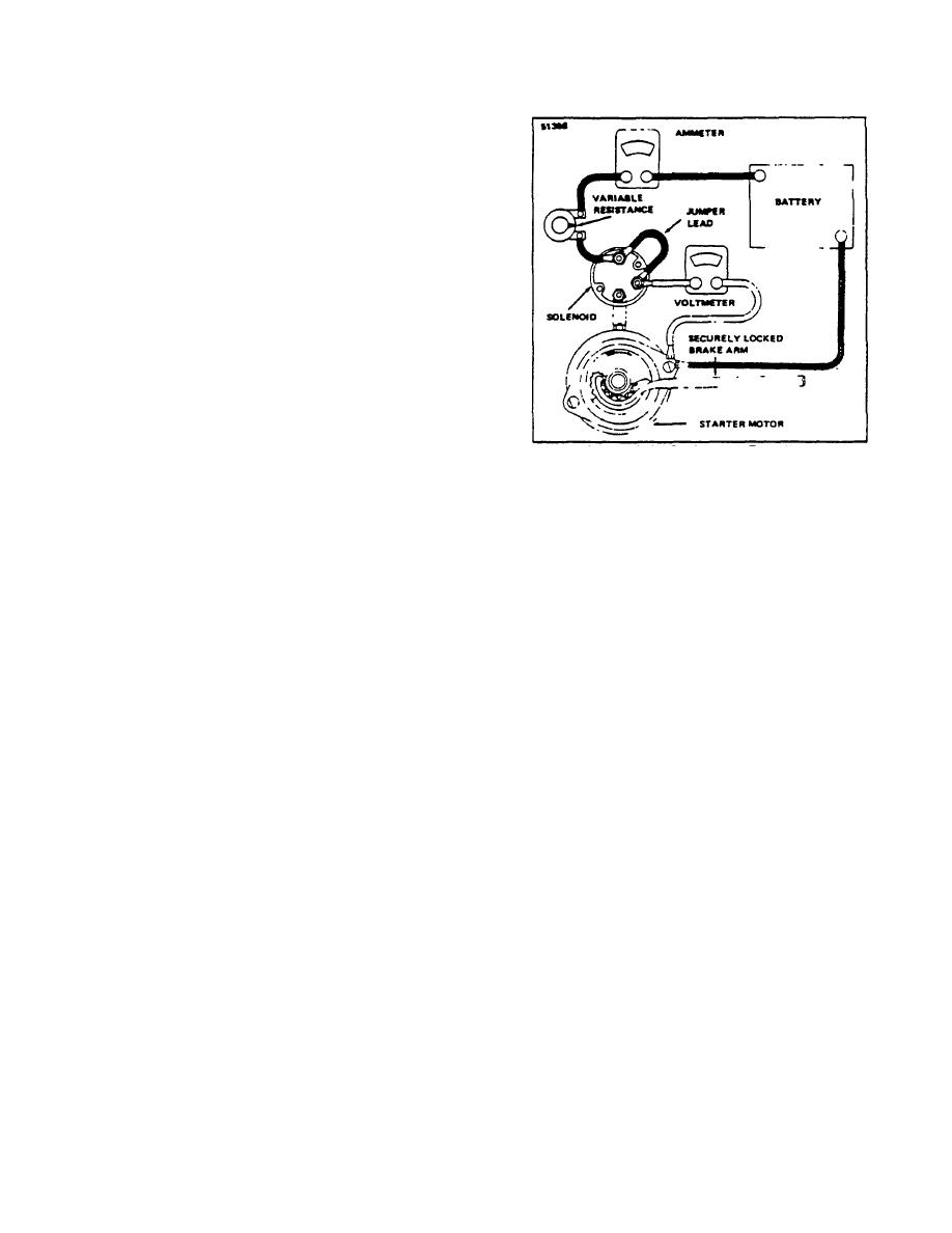
Figure 3-3. Resistance Test Hookup
connections, defective leads, dirty
commutator and causes listed in
Step "d".
3. Remove the commutator end frame and field
frame assembly.
f. High free speed and high current draw
indicate shorted fields. If shorted fields
4. Remove the solenoid and shift lever assembly
are suspected, replace the field coil
from the drive housing.
assembly and check for improved
performance.
5. Remove the armature assembly from the drive
2. Resistance Test
housing.
This test requires equipment as illustrated
6. Remove the thrust collar from the armature
in Figure 3-3. Lock the pinion securely so
shaft.
it cannot rotate.
When the specified
voltage is applied, the current should fall
in a range as Indicated in Starter Motor
7. Remove the pinion from the armature by sliding
Test Specification Chart. A high current
a metal cylinder onto the shaft.
Using a
indicates shorted or grounded conductors,
hammer, strike the metal cylinder against the
and a low current indicates excessive
retainer, driving the retainer toward the armature
resistance.
core and off the snap ring. Refer to Figure 3-4.
F. DISASSEMBLY
8. Remove the snap ring from the groove in the
If the starter does not perform in accordance with the
armature shaft.
specifications, it may need to be disassembled for
further testing of the components. Normally the starter
G. INSPECT AND REPAIR
motor should be disassembled only so far as is
necessary to make repair or replacement of the
1. Brushes and Brush Holders Inspect the brushes
defective parts.
Following are recommended
for wear. If they are worn down to one-half their
instructions for disassembly procedure.
original length, when compared with a new
1. Disconnect the field coil connections from the
brush, they should be replaced. Make certain
solenoid motor terminal.
the brush holders are clean and the brushes are
not binding in the holders.
The full brush
2. Remove the thru-bolts.
surface should ride on the commutator with a
spring tension of 35 oz., to give good, firm
contact. Brush leads and screws should be tight
and clean.
R-146-1
3-94
|
|
Privacy Statement - Press Release - Copyright Information. - Contact Us |
