 |
|||
|
|
|||
|
|
|||
| ||||||||||
|
|
 TM 10-3930-644-14&P
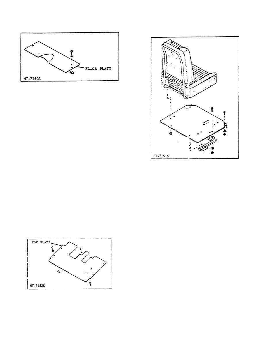
Figure 6. Floor Plate
A. HOOD AND SIDE PANELS
Figures 4 and 5 represent a non-specific., general
representation of the engine hood, side panels and front
engine grille typical to all lift truck models.
1. The side panels are normally secured with a
spring type latch, the disengagement of which
allows side panel -removal for service to engine.
2. The hood, cross assemblies, seat support
assembly, and front grille are all attached with
capscrews, lockwashers and nuts.
To
disassemble, simply study the inter-relationship
of the parts of interest and remove the
Figure 8. Seat Assembly
capscrews, lockwashers, nuts and parts
required for access to component requiring
1. To remove floor and/or toe plate, simply remove
service.
capscrews and lockwashers and lift plate away
from truck.
3. Reverse disassembly procedure, as required, to
reassemble.
2. To install either or both plates, place in correct
position, align holes and replace capscrews and
B. FLOOR AND TOE PLATE
lockwashers.
Refer to Figures 6 and 7 to locate the floor and toe
plates. As a rule the floor and toe plates will require no
C. SEAT ASSEMBLY
maintenance whatever, but are removed during normal
maintenance routine to service items such as
The operator's seat has two vinyl covered, foam rubber
transmission, steering column, brake master cylinder,
cushions; one serves as a backrest and the other as the
etc.
seat cushion. These cushions are contour for maximum
comfort and reduced sliding.
The seat assembly (Fig. 8) has a forward/backward
adjustment to allow for optimum pedal reach as desired
by operator.
1. Should it become me necessary to remove the
operator's seat, simply remove the seat base
assembly mounting capscrews and lift from
truck.
2. To replace the operator's seat, place assembly
in relative mounting position, align all holes and
Figure 7. Toe Plate
insert and secure capscrews and lockwashers.
2-95
|
|
Privacy Statement - Press Release - Copyright Information. - Contact Us |