 |
|||
|
|
|||
|
|
|||
| ||||||||||
|
|
 TM 10-3930-644-14&P
g. While holding lever, observe the needle
L. TILT CYLINDERS
on the pressure gauge. When pressure
reading of 1950 psi is attained, the needle
1. General
will stop, indicating relief valve opening.
The tilt cylinders (Fig 1-8) are used to tilt the
h. If the relief valve opens below or above
mast assembly forward or backward.
The
cylinders, when activated by the control valve,
1950 50 psi, it must be adjusted as
receive oil under pressure in either forward or
follows:
rear ports. As an example, the hydraulic oil
enters the forward ports and forces the plungers
(1) Turn key switch OFF.
backward. At this same moment, hydraulic oil is
forced out of the rear ports of the cylinders by
(2) When pressure gauge reads zero remove
the plunger pistons and is returned to the
relief valve plug.
reservoir through the control valve. When the
hydraulic oil is directed to the rear ports of the
(3) Check relief valve assembly and valve
cylinders, the opposite will occur.
spring for damage.
Replace defective
parts.
2. Inspection
(4) Install valve assembly with spring, 0-ring,
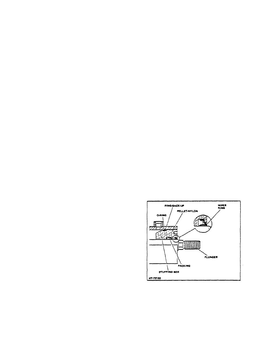
a. Oil Leakage Gland Nut
and plug.
Check for oil leakage at the gland nut. Oil
(5) Repeat steps e through g.
leakage at the gland nut indicates seals
are worn; to stop leakage, remove gland
i. Turn key switch OFF.
nut with a spanner wrench and replace
seals.
j. Remove pressure gauge and tee; then
install hydraulic line to control valve
CAUTION
fittings.
In the following checks 00 NOT
operate the control lever in the
direction opposite to that specified in
the procedure.
K. LIFT CYLINDER
1. General
As previously stated, the lift cylinder
receives hydraulic oil under pressure from
the control valve to raise the lift cylinder
plunger or plungers, depending upon the
type of mast assembly. The hydraulic oil
is applied at the base of the lift cylinder or
near the center or the cylinder and
compels the plunger(s) to extend.
A flow regulator, which is located at the
base of the lift cylinder, controls the/flow of
hydraulic oil so the load lowers at a
controlled rate of speed from the raised
Figure 1-8. Tilt Cylinder
position.
2-89
|
|
Privacy Statement - Press Release - Copyright Information. - Contact Us |
