 |
|||
|
|
|||
|
Page Title:
TOPIC 3. STEERING WHEEL AND COLUMN |
|
||
| ||||||||||
|
|
 TM 10-3930-644-14&P
TOPIC 3. STEERING WHEEL AND COLUMN
A. DESCRIPTION
1. Disconnect battery terminals.
Although the steering wheel and column are similar to
standard steering systems, the power steering system
2. Remove the floor and toe plates.
incorporates a hydraulically operated steer control unit
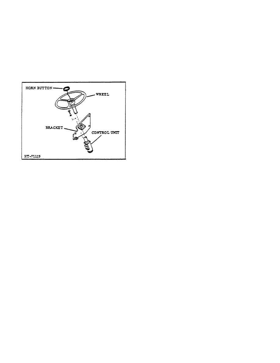
instead of the usual steer gear box. (Figure 5.)
3. Disconnect the hydraulic lines from the steer
control unit.
Tag hydraulic lines for
identification.
NOTE
All hydraulic lines should be plugged
immediately
after
they
are
disconnected to prevent dirt from
entering the system.
4. Disconnect the horn wires from column.
5. Remove the capscrews that hold the steer unit
to the stationary bracket.
6. Lift the steer gear up and out of the vehicle and
place in a clean working area.
NOTE
Figure 5. Power Steer Assembly
Refer to REPAIR MANUAL for
DISASSEMBLY,
INSPECTION,
When the steering wheel is turned in either direction,
REPAIR and REASSEMBLY.
hydraulic fluid is channelled through the appropriate
control unit ports, thus pushing or pulling the drag link,
D. INSTALLATION
which controls direction of wheels.
1. Place the-steer gear control unit in Its r lative
e
B. STEERING COLUMN ADJUSTMENT
mounting location at end of steering column and
insert and tighten securing capscrews.
Proper alignment the steering column is very important.
The column must not be sprung in any direction from its
2. Reconnect the horn wires.
free position. To determine whether or not misalignment
exists, release the upper column support and note
3. Unplug and connect the hydraulic lines to steer
whether column moves to a different position-its free
unit as they were removed.
position. If it does move, then it has been out of line and
should be clamped in proper position.
or position
4. Ensure that reassembly is complete, then
corrected at mounting bracket on truck. If column has
replace the floor and toe plates.
been bent permanently because of severe misalignment,
then replacement of the tube, shaft, or entire unit may be
5. Reconnect the battery terminals.
necessary.
If the steering system requires adjustment, refer to
C. REMOVAL
Paragraph D in preceding Topic 2.
The following procedure is recommended for proper
steer control unit removal:
TOPIC 4. DRAG LINK
Refer to POWER STEER CYLINDER TOPIC for
REMOVAL and INSTALLATION.
2-82
|
|
Privacy Statement - Press Release - Copyright Information. - Contact Us |
