 |
|||
|
|
|||
|
|
|||
| ||||||||||
|
|
 TM 10-3930-644-14&P
A. DESCRIPTION
NOTE
Refer to REPAIR MANUAL for
The master cylinder mad hydraulic fluid reservoir are
MASTER CYLINDER, INSPECTION,
combined in one casting and are joined by intake and
DISASSEMBLY,
REPAIR
and
by-pass
ports
located
in
the
cylinder
wall.
REASSEMBLY.
(See Figure 3.) Internal parts are removed or installed at
the push rod end of the cylinder. The stop plate holding
C. INSTALLATION
the internal parts is retained by a lockwire clipped into
the cylinder bore.
The cylinder piston is operated
1. Ensure that master cylinder is completely
through a push rod connected to the brake pedal. The
reassembled prior to installing.
push rod and cylinder opening is enclosed with a rubber
2. Replace master cylinder assembly in its relative
boot.
mounting
location
and
install
securing
It is impractical to thoroughly clean the cylinder and fluid
capscrews.
reservoir an the truck. For this reason the following
3. Attach brake pedal pushrod to cylinder and
instructions should be observed:
secure with clevis pin previously removed.
4. Connect brake hydraulic line to cylinder.
B. REMOVAL
5. Refer to LUBRICATION CHART and fill cylinder
with proper high grade hydraulic brake fluid.
1. Remove floor and toe plate.
SAE specification R-71 is recommended.
2. Disconnect brake hydraulic line attached to
6. Bleed brake system as outlined under
master cylinder.
appropriate heading, REPAIR MANUAL.
3. Remove clevis pin holding the pushrod to the
7. Replace floor and toe plate.
brake pedal assembly.
4. Remove capscrews that mount the master
cylinder to the inside of the truck frame and
remove.
TOPIC 3. DRIVE WHEEL BRAKES
A. DESCRIPTION
In order for the self-adjusting brakes to operate property,
the self-adjuster assembly must be properly torqued. If it
The brake shoes are self-adjusting through the use of a
becomes necessary to re- move and disassemble the
friction operated self-adjuster in each drive wheel. The
self-adjuster in the field, use the following recommended
friction between the two slide assemblies of the self-
procedure to assemble the self-adjuster.
adjuster is great enough to prevent the brake shoe
springs from fully retracting the self-adjuster, but not
B. ADJUSTMENT
great enough to prevent the hydraulic pressure from :
expanding it. The self-adjuster assembly is mounted to
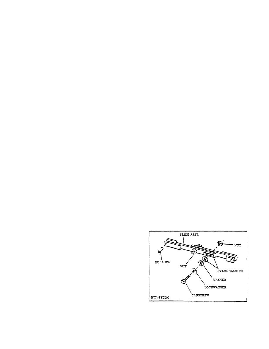
1. Assemble components as Illustrated in Figure 4.
the brake shoes with roll pins. The roll pin holes in the
brake shoes are 1/32" oversize to provide proper
working clearance between the brake shoe lining and
drum.
CAUTION
Exercise care when self-adjuster is
handled or installed. Do cont bend
the tags of the slide assemblies in
any way because the holes for the
roll pins must be parallel with each
other. If the holes are ac parallel, the
roll pins will lie at a slight angle
through the mounting holes in the
brake shoes. Improper alignment of
the roll pins could lead to improper
brake shoe retraction due to lack of
Figure 4. Brake Self-Adjuster Assembly
proper roll pin clearance in the brake
shoe holes. This in turn could create
brake shoe drag on the drum.
2-77
|
|
Privacy Statement - Press Release - Copyright Information. - Contact Us |
