 |
|||
|
|
|||
|
Page Title:
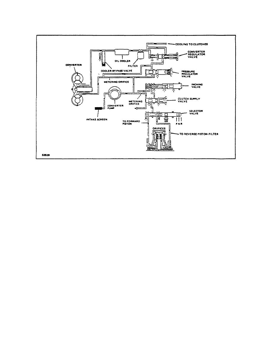
Figure 1-2. Power Shift - Hydraulic Schematic |
|
||
| ||||||||||
|
|
 TM 10-3930-644-14&P
Figure 1-2. Power Shift - Hydraulic Schematic
In normal Lift Truck operation the turbine turns at a
engine) to keep the impeller running against this
slower speed than the Impeller an since both are the
resistance. In the turbine the oil is slowed down and
same dimension, the centrifugal force on the oil in the
presses forward against the vanes, and when the turbine
impeller is always greater than that of the oil in the
is moving under this force, power to drive the truck is
turbine. It is this difference plus the pressurized oil from
produced. Thus, all the oil passing through the impeller
the pump which causes the oil to circulate in and through
picks up energy and gives it to the turbine. Up to this
the converter.
point operation is the same as a fluid coupling and there
is no torque multiplication.
From the above it can be seen that the oil in the
converter has a dual motion. It travels with the impeller
To transmit velocity to the oil at the inner circumference
and the turbine around the outer circumference of the
of the converter, a third member, the stator, is added to
converter and it also flows around the inner
the fluid coupling, between the impeller and the turbine.
circumference or central core of the converter. As a
It is here that the fluid coupling becomes a torque
result of these motions the oil carries a certain amount of
converter. With the impeller rotating and the turbine
kinetic energy. The velocity of the oil in the converter
stalled, the oil is driven through the curved blades of the
increases as the oil passes through the impeller to the
turbine.
The curved blades redirect the oil in the
turbine and decreases as it passes through the turbine
opposite direction from which it was received. As the oil
back to the impeller.
leaves the turbine blades, it strikes the stator blades
causing a reaction which produces torque multiplication.
Since the velocity increases in the impeller, its kinetic
energy increases and this gain in kinetic energy can
The stator directs the oil back to the impeller where any
come only from the impeller. That is to say, when
remaining kinetic energy combines with the kinetic
increasing the velocity of oil in its vanes, the impeller
energy of the impeller oil,
encounters a resistance, and it takes power (from the
M-171-1
2-50
|
|
Privacy Statement - Press Release - Copyright Information. - Contact Us |
