 |
|||
|
|
|||
|
|
|||
| ||||||||||
|
|
 TM 10-3930-644-14&P
TOPIC 8. GOVERNOR
A. GOVERNOR DESCRIPTION
C. INSPECTION
The governor prevents engine speed from exceeding a
1. Wash governor in a clean solvent and dry with
predetermined maximum. The governor is mounted
compressed air.
between the carburetor and manifold flanges. It consists
of a main body, which contains a throttle shaft, a throttle
2. Check governor for wear, cracks or damaged
valve and a main governor spring. The main governor
surfaces.
spring is attached by linkage to the governor shaft and
the spring force holds the throttle valve open.
D. INSTALLATION
When the engine starts, air flows through the carburetor
1. Install new gaskets and spacer on carburetor.
throat and the governor throat. The velocity of the air
creates a pressure above the throttle valve. When this
2. Position governor on carburetor and connect
force exceeds the force exerted by the spring, the
manifold fitting. Secure with studs, lockwashers
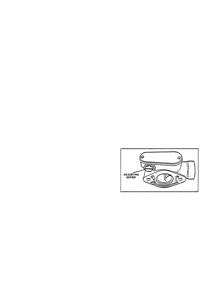
throttle will move to a closed position. The adjusting
and nuts.
screw varies the spring tension (Figure 10).
3. Install lock wire and seals.
When the closing action of the valve exactly balance the
spring, governing action takes place and maximum
E. GOVERNOR ADJUSTMENT
speed is foxed at this point.
NOTE
When load is applied the velocity of the gas through the
The desired engine speed is obtained
manifold and the pressure against the governing valve is
by increasing or decreasing the
reduced and the spring opens the valve to feed more
governor spring tension.
gasoline to the engine to handle the increased load
demand. This maintains an almost constant speed
Turn adjusting screw (Figure 10) in or out, to increase or
whether the engine is running with or without load.
decrease pull on the spring.
B. GOVERNOR REMOVAL
1. Remove the nut, lockwasher and stud securing
the governor to the carburetor.
2. Disconnect the governor from the manifold fitting
and remove lock wire and seals.
3. Remove governor, seals and spacer from the
carburetor.
Figure 10. Velocity Governor
2-22
|
|
Privacy Statement - Press Release - Copyright Information. - Contact Us |