 |
|||
|
|
|||
|
|
|||
| ||||||||||
|
|
 TM 10-3930-644-14&P
TOPIC 4. FUEL TANK
A. DESCRIPTION
2. Replace filler cap assembly.
The fuel tank is of steel construction with welded seams.
3. Loosen dr ain plug.
It includes a fuel level sender unit and a filler cap with
filter screen. The fuel tank requires little, if any service
4. Inspect for water contamination.
other than periodic cleansing of the fuel filter screen.
5. If contaminated, drain until water is emptied,
B. CLEANING AND INSPECTION
then close valve.
1. Remove fil!er cap assembly and check filter
screen for fouling. Clean if required, and dry
6. Connect outlet fuel line and fill tank to
with compressed air.
recommended capacity with proper octane fuel.
7. Check tank and fuel lines for leaks.
Repair if
necessary.
TOPIC 5. FUEL PUMP AND FUEL FILTER
A. DESCRIPTION
operating rocker arm.
Pressure should be
between 2-3/4 p.s.i. to 3 p.s.i. Pressure should
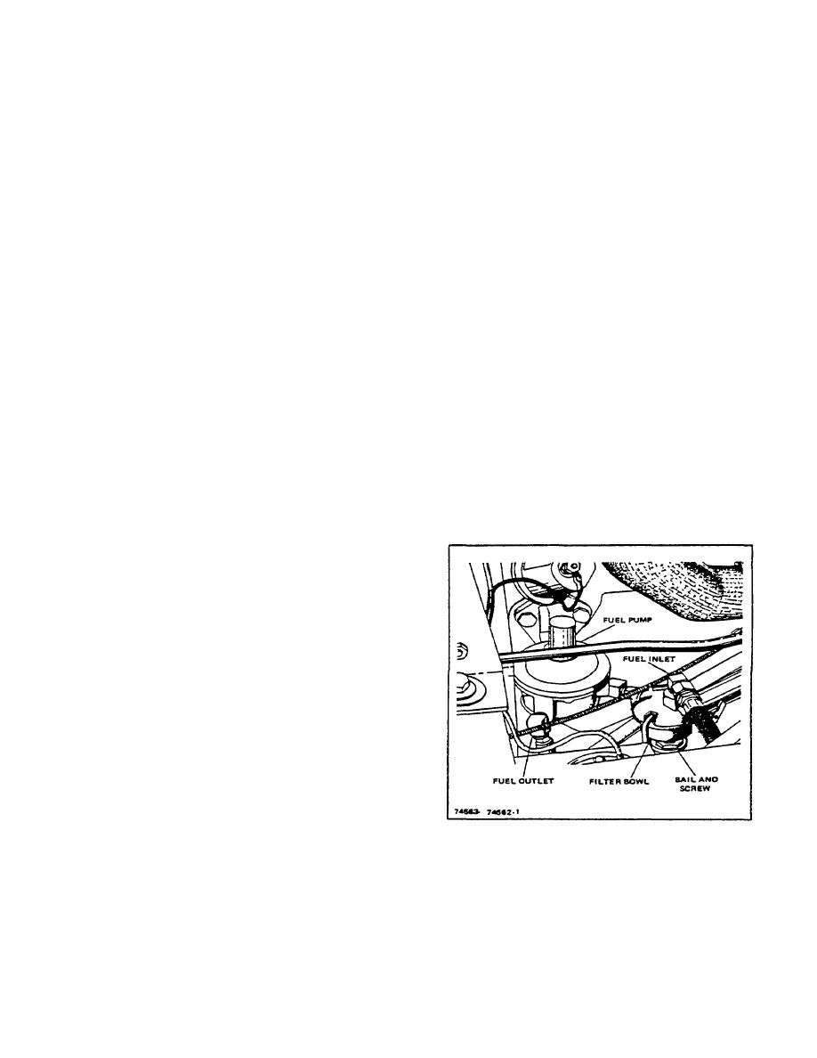
The fuel pump is a mechanical diaphragm type pump
not fall off rapidly.
with a strainer and sediment bowl.
The pump is
9. Install fuel pump as removed, ensuring new
mounted on the left side of the engine and is operated
mounting gasket is used.
by an eccentric cam on the engine camshaft.
10. Install and secure capscrews and lockwashers.
11. Connect inlet and outlet fuel lines. Do not over
Fuel from the tank enters the strainer-sediment bowl on
tighten connections.
the suction stroke of the pump and is forced to the
carburetor on the pressure stroke. Action is controlled
by two valves in the cover assembly.
B. REMOVAL AND INSPECTION
1. Disconnect fuel pump inlet and outlet lines.
2. Remove capscrews and lockwashers from fuel
pump mounting flange and remove pump.
3. Clean pump with solvent and dry with
compressed air.
4. Remove bowl and bowl gasket.
5. Remove strainer screen from top cover and
discard.
6. Install new strainer screen after ensuring that it
shows no damage or obstruction. New screen
must fit snugly around inner and outer edges.
7. Install new bowl gasket, swing bail assembly
into position over bowl, and tighten nut securely.
8. Test operation of pump valve by attaching
Figure 5-1. Pump Mounting
pressure
gauge
to
outlet
and
M-123-1
2-19
|
|
Privacy Statement - Press Release - Copyright Information. - Contact Us |