 |
|||
|
|
|||
|
|
|||
| ||||||||||
|
|
 TM 10-3930-644-14&P
4. Refer to paragraph I for static ignition timing and
paragraph J for dynamic ignition timing.
5. If distributor is not going to be removed, install
contact set, if removed. Be certain that points
are in perfect alignment (Figure 5-3 and 5-4).
NOTE
Following data is required for proper
distributor to engine timing.
F. DISTRIBUTOR CHARACTERISTICS
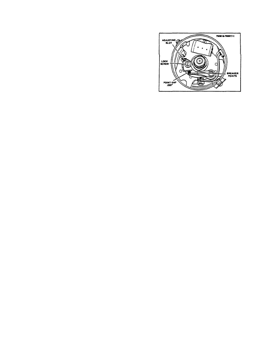
Figure 5-4. Adjusting Contact Gap (Type II Distributor)
Type II Distributor
Rotation ..................................C.C.W. (Viewing Rotor)
2. Slightly loosen the contact assembly locking
screw Figure 5-3 and 5-4).
Point Opening ..................................................020"
Cam Angle Range ......................................66 - 72
Start Advance (T.D.C.) ............................. 500 RPM
3. Insert a feeler gauge between the contact
points, insert a screwdriver in the adjusting slot
G. STATIC BREAKER POINT ADJUSTMENT
and turn clockwise or counterclockwise to
specified point gap. When properly adjusted a
slight drag will be felt when feeler gauge is slid
NOTE
between the points.
Refer to paragraph F for correct point
gaps and cam angles for the
4. Tighten locking screw and recheck gap for
distributor being serviced.
accuracy.
1. Nudge the starter switch until the breaker arm is
5. Replace dust seal, rotor and distributor cap.
resting on the high point of the cam. Attach a
remote starter switch between the battery
positive (+) terminal and the starter solenoid
H. DYNAMIC BREAKER POINT ADJUSTMENT
switch terminals. The truck starter switch can be
used but a remote switch is more convenient.
1. Disconnect high tension coil lead from distributor
and ground to engine-or frame.
2. Attach positive lead of dwell meter to the
negative terminal (-) of coil. Connect negative
dwell meter lead to ground.
3. Attach a remote starter switch between the
battery positive terminal (+) and the starter
solenoid terminal. The truck starter switch can
be used but the remote switch is more
convenient.
4. Remove distributor cap, rotor and dust seal.
Slightly loosen the contact assembly locking
screw and insert a screw driver in the adjusting
slot (Figure 5-3 or 5-4).
5. Use starter to crank the engine. Observe the
dwell meter. The meter will rise to a value and
then drop off each time the points open. Turn
the screwdriver in the adjusting slot until the
maximum value of the needle rise equals the
required dwell specification. See paragraph F.
M-104-1
2-8
|
|
Privacy Statement - Press Release - Copyright Information. - Contact Us |
