 |
|||
|
|
|||
|
|
|||
| ||||||||||
|
|
 TM 10-3930-644-14&P
TOPIC 2. VALVE ADJUSTMENT
A. DESCRIPTION
4. Place thumb over the spark plug opening and
slowly crank the engine until an outward
The valve tappets (Figure 2-1) are removable. These
pressure can be felt. Pressure indicates number
large, barrel shaped, pressure lubricated tappets are so
one piston is moving toward Top Dead Center of
designed that by removing the adjusting screw, the main
the compression stroke. Continue cranking until
body can be lifted out and replaced from above through
the timing mark on the flywheel is in center of
the valve chamber. This eliminates the costly service
the flywheel housing timing hole. Both valves
operation of dropping the oil pan and pulling the
are then closed on the compression stroke of
camshaft. Locking of the adjustment is both simple and
number one cylinder.
effective.
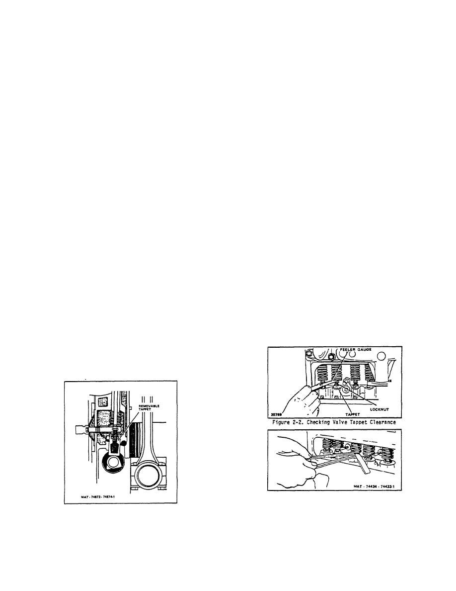
5. Use two thin wrenches when adjusting valve
Accurate valve tappet settings materially prolong engine
clearance. Use the lower wrench to hold the
life and aid performance.
in addition to impairing
tappet and the upper wrench to raise or lower
performance, excessive clearances are detrimental to
the tappet adjusting screw. When the valve lash
cams and tappets as well as to the rest of the valve
is properly adjusted, the appropriate feeler
mechanism.
When clearances are too low, the
gauge should pass between the tappet and its
possibility of burned valves increases.
corresponding valve stem with a slight drag
(Figures 2-2 and 2-3).
B. ADJUSTMENT
Check and adjust intake and exhaust tappets to
6. Crank the engine one-half revolution at a time
following clearances at running temperature:
and check the clearance of each valve; adjust if
necessary. Do this on each set of cylinder
Intake - .012"
valves in succession according to the firing order
Exhaust - .020"
of the engine, which is 1-3-4-2.
To adjust valve tappets proceed as follows:
7. Install new gasket and install valve tappet cover.
Check to see that the valve cover makes an oil-
1. Disconnect and ground the high tension coil wire
tight seal with the crankcase.
to prevent accidentally starting the engine.
8. Replace the spark plug, spark plug wire and coil
2. Remove the valve tappet cover from the left side
wire.
of the crankcase.
3. Remove the spark plug from number one
cylinder.
Figure 2-3. Adjusting Valve Tappet Clearance
Figure 2-1. Removable Valve Tappet
2-4
|
|
Privacy Statement - Press Release - Copyright Information. - Contact Us |
