| |
TM 10-3930-643-34
GENERAL SUPPORT PROPELLER AND PROPELLER SHAFTS MAINTENANCE.
16-3.
Rear Differential Carrier Assembly. (Sheet 2 of 12)
DISASSEMBLY
1.
2.
3.
4.
5.
NOTE
Prior to disassembly of differ-
ential assembly, backlash of gears
must be measured
and
recorded.
Steps 1 thru 3 are necessary only
if gears are to be reused.
Except where noted, The follow-
ing disassembly procedure for
the differential assembly is
identical for both vehicles S/N
2001 to 2903 and S/N 2000 and
below and 2904
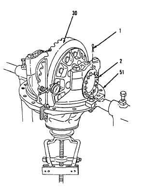
Position dial
shown.
Secure flange
(30) back and
and above.
scale
indicator as
yoke and rotate gear
forth.
Record backlash as indicated on dial
scale indicator.
Using a 1-1/2” socket and socket
wrench handle, remove flange yoke.
Using side cutting pliers, remove two
cotter pins (1) and adjustment rings
(2) from carrier (51).
Discard
cotter pins (l).
Go to sheet 3
16-20
|

