| |
TM 10-3930-643-34
GENERAL SUPPORT PROPELLER AND PROPELLER SHAFTS MAINTENANCE.
16-1.
Front Differential Carrier Assembly. (Sheet 8 of 13)
ASSEMBLY
NOTE
The following steps (41 thru 55)
is the assembly procedure for
differential carrier assembly for
vehicles S/N 2001 to 2903. The
assembly procedure for differential
carrier assembly for vehicles S/N
2000 and below and 2904 and above,
proceed to steps (56 thru 68).
When replacing parts, gears must
be replaced as a matched set.
Side gear thrust washers must be
replaced as a matched set.
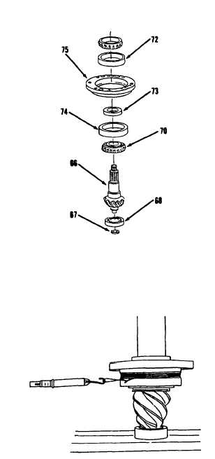
41.
Install cup (74), spacer (73) and cup
(72) to cage (75).’
42.
Install cone (70) and bearing (68) to
gear (66).
43.
Install ring (67).
44.
Using arbor press, install gear (66)
in cage (75).
45.
Install cone (69).
46.
Rotate cage (75) to verify normal
bearing contact.
47.
Apply load of 6 tons with press as
shown.
48.
Using soft iron wire and scale
indicator, measure bearing preload
torque as shown. Bearing preload
torque should be 5 to 15 in-lb. Be
sure to measure rotating torque and
not starting torque.
Install thinner
spacer (73) to increase or thicker
spacer (73) to decrease preload as
required.
Go to sheet 9
16-9
|

