| |
TM 10-3930-643-34
FRAME AND TOWING ATTACHMENTS MAINTENANCE. (cont)
10-2.
Frame Hinge Pin and Frame Assembly.
ADJUSTMENT (cont)
(Sheet 5
23.
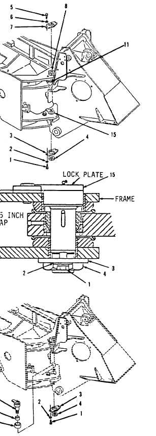
Using a 15/16" socket and socket
wrench handle, install retainer plate
(3), two washers (2) and bolts (1).
Retainer plate (3) can be turned over
if it does not aline with nut (4).
If retainer plate (3) still does not
aline with nut (4), do not turn more
than 30 degrees.
NOTE
The following step is the proce-
dure used to acquire 0.0625 inch
gap between shafts lock plates and
frame ears.
24.
Using bottle jacks, support frames to
allow removal of shaft (15) or shaft
(11).
Do not remove both shafts from
frame at the same time.
If both
shafts need adjustment, remove one
at a time.
NOTE
The following steps are for
adjusting lower hitch shaft.
Adjustment of upper hitch shaft
is identical,
except as noted.
of 13)
25.
26.
27.
Remove steering linkage before
removal of upper hitch shaft, refer
to TM 10-3930-643-20.
Using a 15/16" socket and socket
wrench handle, remove two bolts (1),
washers (2) and retainer plate (3).
Using a 3-1/16" socket and socket
wrench handle, remove nut (4).
Go to sheet 6
10-10
|


