| |
TM 10-3930-643-34
FRAME AND TOWING ATTACHMENTS MAINTENANCE.
10-2.
Frame Hinge Pin and Frame Assembly. (Sheet 4 of 13)
ADJUSTMENT
16.
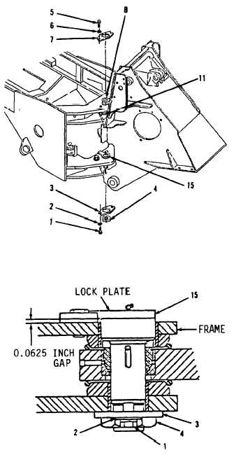
Using a feeler gage, measure
clearance between lock plates and
frame ears.
Shafts (11 and 15) and
their lock plates must not make
contact with frame ears.
A minimum
of 0.0625 inch must exist between
lock plate and frame.
If clearance
is incorrect, refer to step 29 for
shim installation.
17.
Using a 15/16" socket and socket
wrench handle, install retainer plate
(7), two washers (6) and bolts (5).
Retainer plate (7) can be turned over
if it does not aline with nut (8).
If retainer plate (7) still does not
aline with nut (8), loosen or tighten
nut (8).
Do not turn nut more than
30 degrees.
18.
Using a 3-1/16" socket, socket wrench
handle and torque wrench, install nut
(4) and tighten to 190 lb-ft. Tap
head of shaft (15) solidly with hammer
while tightening nut (4) to seat shaft
(15).
19.
Loosen nut (4).
20.
Tighten nut (4) by hand with retainer
plate (3).
21.
Raise forklift to maximum height and
lower in jerky increments. This will
help to seat mating components.
22.
Recheck vertical frame movement with
dial indicator, refer to step 6. If
dial indicator reading still exceeds
0.010 inch, determine if movement is
all up and down.
If movement is
anything but vertical, replacement of
worn parts is necessary.
If measure
exceeds 0.010 inch and is all up and
down, repeat steps 18 and 19.
Increase tightening of nut (4) to 220
lb-ft.
Go to sheet 5
10-9
|

