| |
TM 10-3930-643-34
STEERING TROUBLESHOOTING AND MAINTENANCE.
9-2.
Steering Gear Assembly. (Sheet 6 of 8)
ASSEMBLY
23.
24.
25.
26.
27.
28.
NOTE
If balls are stopped by reaching
end of worm,
hold down balls
already installed with
rod or
punch.
Rotate shaft in a reverse
direction a few turns.
Filling of
circuit may then be continued.
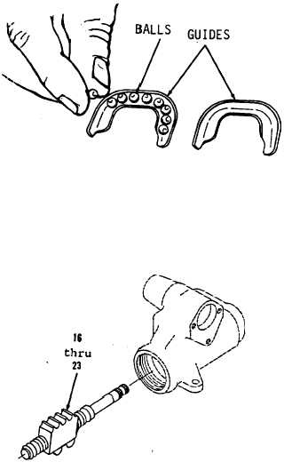
Place remaining balls (20) in groove
of one guide (19). Then cover with
another guide (19).
Plug both ends of guides (19) with
multi-purpose grease to prevent balls
(20) from falling out
when
installing.
Using long round nose pliers, install
items 20 and 19 as an
assembly in
ballnut and worm assembly (21).
NOTE
Install remainder of balls by
repeating steps 18 thru 25.
Install 27 of 54 balls (20) in
ballnut and worm assembly (21).
Using a 3/8” socket and socket wrench
handle, install clamp (18), washer
(17) and bolt (16).
NOTE
Do not allow ballnut
end of worm threads.
tape exposed threads
for assembly.
to rotate to
Temporarily
until
ready
Test items 23 thru 16 as an assembly
by rotating ballnut on worm.
Ballnut
and worm assembly (21) must
move
freely.
Go to sheet 7
9-11
|

