| |
TM 10-3930-643-34
ENGINE, FUEL, EXHAUST AND COOLING
4-14.
Fuel Injection Pump, Cover
INSTALLATION (cont)
40.
41.
42.
43.
TROUBLESHOOTING AND MAINTENANCE. (cont)
Plate, Adapter and Drive Gears. (Sheet 8 of 9)
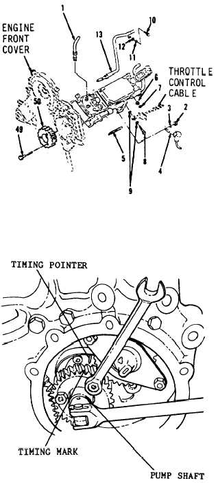
Using a 9/16” socket and socket
wrench handle,
install washer (12),
lock washer (11) and bolt (10).
Position throttle control cable.
Using a 7/16” socket, socket
wrench
handle, a 7/16” open end wrench and
long round nose pliers, install two
washers (9), bolt (8), washer (7),
nut (6) and spring (5).
Using a flat tip screwdriver, install
terminal (4), washer (3) and nut (2).
Apply silicone sealant over entire
connection.
Using a 3/4” open end wrench, install
six fuel injector lines (1).
Tighten
fittings to 35 lb-ft.
TIMING
44.
Rotate
piston
timing
engine clockwise till number
is on compression stroke and
pointer is at 15 % BTDC plus
1
or minis one percent.
45.
Using a 7/8 socket and socket wrench
handle, rotate pump shaft until
timing mark on shaft lines up with
timing pointer.
Make sure timing marks on
drive gear and idler gear are
in alignment.
46.
Install drive gear (50), aligning the
timing marks with the idler gear.
GO to Sheet 9
4-100
|

