| |
TM 10-3930-643-20
HYDRAULIC SYSTEM TROUBLESHOOTING AND MAINTENANCE.
14-3.
Fork Control Lever Assemblies. (Sheet 6 of 7)
INSTALLATION
40.
41.
42.
43*
44.
45.
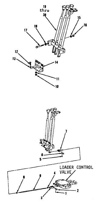
Using two 9/16" combination
wrenches, install two washers (18),
screws (17), washers (16) and nuts
( 1 5 ).
Using a 3/4” socket, socket wrench
h a n d l e a n d a 3 / 4 ” c o m b i n a t i on
wrench, install hinge
( 1 4 ) , t wo
washers (13), screws (12),
washers
(11) and nuts (10).
Using a 1/2" open end wrench,
install rod (9), nut (8) and clevis
(7) from under right side of cab, to
l e v e r ( 2 7 ).
Using long
r o u n d n o s e p l i e r s ,
install pin (6) and new cotter pin
( 5 ).
Using a 1/2” open end wrench,
install nut (4) and clevis (3).
Using long
r o u n d n o s e p l i e r s ,
install pin (2) and new cotter pin
(1) to fork control valve.
Go to sheet 7
14-13
|

