| |
TM 10-3930-643-20
BRAKE TROUBLESHOOTING
8-8. Brake Hydraulic
REMOVAL
1.
2.
3.
4.
5.
6.
7.
8.
AND MAINTENANCE.
Hoses, Lines and
(cont)
Fittings. (Sheet 2 of 11)
NOTE
• The following are differences
between M10A Forklift models.
Removal/installation procedures
for both are identical except as
noted.
• Tag all hose and tube assemblies
before disconnecting to aid in
i n s t a l l a t i o n . P l a c e s u i t a b le
container under disconnected
points.
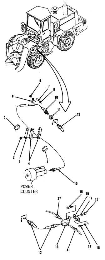
Using a 3/4” open end wrench,
disconnect hose assembly (10) from
l e f t s i d e o f p r e s s u r e c o n v e r t e r/
power cluster.
Using side cutting pliers, cut and
discard four tie straps (1).
Using a 9/16” open end wrench,
remove two nuts (2), link (3) and
clamp (4) from right side, center of
v e h i c l e.
Using side cutting pliers cut and
discard tie strap (5).
Using a 9/16” socket and socket
wrench handle, remove two nuts (6),
washers (7), clamps (8) and washers
( 9 ).
Using
1/2”
and
1“
open
end
wrenches and
11/16”
socket
and
socket wrench handle, remove
hose
assembly (10) and nut (11).
Using an 11/16” open end wrench,
remove hose assembly (12).
Using a 7/16” open end wrench,
disconnect tube assemblies (27 and
41) from front of rear axle.
Go to sheet 3
8-26
|

