| |
TM 10-3930-638-24&P
4 - 4 . T R A N S M I S S I O N M A I N T E N A N C E ( c o n t)
f. Reverse and Second Clutch Assembly (cont).
STEP
LOCATION
ITEM
ACTION
REMARKS
REASSEMBLY (cont)
CAUTION
Use care to not damage inner and outer seals.
13
Reverse
a. Clutch piston (19)
Install
clutch
b. Piston return spring position
side
spacer (15)
c. Five piston return
Install
springs (17)
d. Retaining ring (16)
Posit ion
e.
f.
g.
h.
i.
j.
k.
l.
Piston return spring
spacer (15)
Retaining ring (16)
outer clutch disc (14)
Inner clutch disc (13)
Outer clutch disc (14),
inner clutch disc (13)
Clutch disc backing
plate (12)
Retaining ring (11)
Clutch driven gear
Compress
Install
Install
Install
Install
Install
Install
Install
bearing (10)
m. Retaining ring (9)
Instsll
n. Bearing spacer (7)
Install
o. Retaining ring (6)
Install
CAUTION
Do not force this procedure.
Position first piston return spring
with curved side up, then alternate
remaining piston return springs
On drum and plug assembly (18)
Use sleeve installed in press
Install retaining ring through opening in
sleeve; remove sleeve after installation
Install one outer clutch disc
Install one
Install remaining discs, alternating between
outer clutch discs and inner clutch discs.
The last disc installed is inner clutch disc
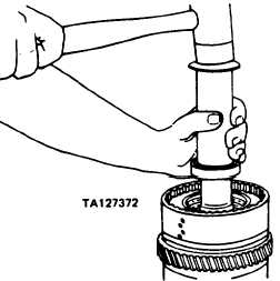
Use mallet and sleeve
p. Reverse clutch gear
Install
Align splines on hub with internal teeth of
and hub assembly
discs. Tap hub gently into. position. Hub
(5)
splines must be in full position with inter-
nal teeth of all discs
Change
1
4-203
|

