| |
TM 10-3930-638-24&P
4-3. FUEL SYSTEM MAINTENANCE (cont)
b. Fuel Injection Pump (cont).
STEP
LOCATION
ITEM
ACTION
REMARKS
REASSEMBLY (cont)
32
NOTE
(cont)
In following steps where grease is used to keep parts together to
ease assembly, use grease sparingly as it can plug return fitting
and pump will not bleed air from housing during start-up.
g. Governor
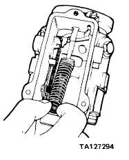
Assemble
Assemble these four parts on bench. Apply
spring (45)
a small amount of grease to these parts to
h. Spring retainer (46)
Assemble
keep them in place while assembling.
i. Idle spring (47)
Assemble
Loosen guide stud and withdraw it just
j. Idling spring
Assemble
enough to install these parts on it.
guide (48)
Tighten guide stud to 110-115 pounds
inch torque
k. Two washers
(35 and 39)
and seals
(34 and 38)
1. Throttle shaft
assembly (37)
m. Throttle shaft
lever (36)
Install
Install
Install
On throttle shaft assembly (37) and shutoff
shaft (33). Apply a light film of grease to
each seal
Partially through its bore
Slide over throttle shaft assembly (37) so
that projection in lever (36) bore engages
keyway in shaft (37). Position forked end
of lever (36) so that it straddles guide stud
(44)
4-123
|

