| |
TM 10-3930-638-24&P
4-2. ENGINE MAINTENANCE (cont)
d. Crankshaft and Main Bearings (cont).
STEP
LOCATION
ITEM
ACTION
REMARKS
INSTALLATION (cont)
17
cont)
18
19
20
Connecting
rod bearing
cap (2)
Crankshaft
(8)
Cylinder
block
e. Plasti gage
Bearing liner
Connecting rod
journals
a. Four connecting
rod bearing
caps (2)
b. Eight connecting
rod nuts (1)
c. Front main bearing
cap (4)
d. Oil pump
e. Crankshaft gear
(9) and camshaft
gear
Measure
Lubricate
Lubricate
Position
Install
Position
Install
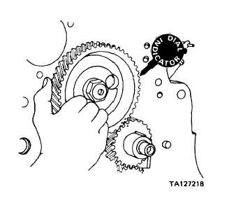
Check back-
lash
Flattened plasti gage located on bearing
cap liner or crankshaft journal. Measure
widest point. Oil clearance shall be
0.0010 to 0.0040 inch. If necessary,
install undersize bearing liners to obtain
this dimension
Located in bore of bearing caps; use
No. 30 oil
Use No. 30 oil
Tighten to 45-50 pounds foot torque
Para 4-2i
Place dial indicator on camshaft gear. Back
lash between gear (9) and camshaft gear
shall be 0.0002 to 0.006 inch. If back-
lash exceeds 0.006 inch, replace gears
NOTE
Excessive backlash may also be caused by
worn camshaft bushings.
4-36
|

