| |
TM 10-3930-638-24&P
4-2. ENGINE MAINTENANCE (cont)
a. Cylinder Block Assembly (cont).
STEP
LOCATION
ITEM
ACTION
REMARKS
REASSEMBLY (cont)
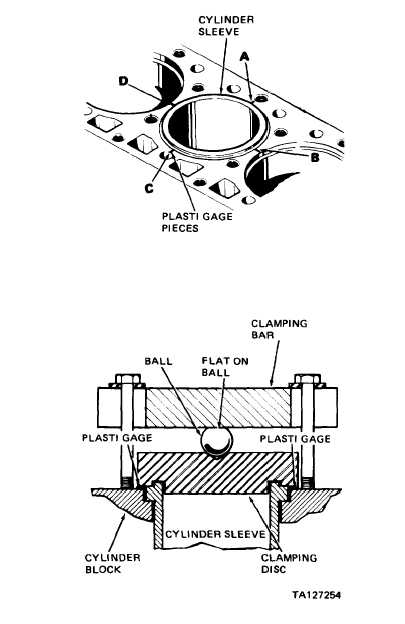
b. Measure sleeve
Position plasti gage at four points shown.
(cont)
protrusion
Plasti gage must not protrude onto sleeve
flange. Install clamping disc tool care-
fully over sleeve as shown. Install 1 inch
ball and clamping bar. Tighten hold dew]
bolts evenly to 50 pounds foot torque.
Then, remove clamping bolts, bar and
ball. Carefully remove clamping disc so
as not to disturb plasti gage. Flattened
plasti gage will be on clamping disc or
block. Measure plasti gage. If sleeve pro-
trusion varies more than 0.005 inch
around circumference, replace that sleeve
and recheck
4-8
|