| |
TM 10-3930-638-24&P
3-9. ALTERNATOR TROUBLESHOOTING (cont)
MALFUNCTION
TEST OR INSPECTION
CORRECTIVE ACTION
2. IMPROPER OUTPUT CURRENT
Step 1.
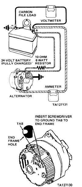
Connect test set-up to alternator as illustrated.
Operate alternator at moderate speed and adjust carbon
pile for maximum indication on ammeter.
Note ammeter indication.
a. If ammeter indicates 27 to 47 amperes, and volt-
meter indicates less than 31 Vdc, alternator
operation is normal.
b. If ammeter does not indicate 27 to 47 amperes,
proceed to step 2.
Step 2.
CAUTION
Tab is within 3/4 inch of casting surface. Do not
force screwdriver deeper than one inch into alter-
nator end frame.
Insert screwdriver into test hole in end frame and
ground tab as shown; then repeat step 1.
a. If ammeter indicates 27 to 47 amperes, check
field winding and regulator (para 3-12).
b. If ammeter does not indicate 27 to 47 amperes,
check the alternator field winding, diode trio,
rectifier bridge and stator (para 3-12).
3-10. STARTER AND SOLENOID TROUBLESHOOTING
1. STARTER TROUBLESHOOTING
NOTE
Compare results of starter no-load test (STARTER CRANKS TOO
SLOWLY, para 2-21) with the following chart and then refer to
paragraph 3-13:
3-90
|

