| |
TM 10-3930-638-24&P
2-38. TRANSMISSION MAINTENANCE (Cont)
b. Transmission Linkage Controls (cont).
STEP
LOCATION
ITEM
ACTION
REMARKS
ADJUSTMENT (cont)
21
Instrument panel
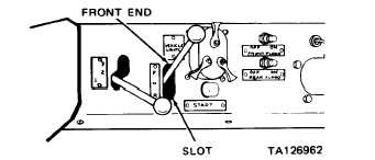
a. Direction control
a. Move into for-
lever (24)
ward (F)
position
b. Measure clear-
ance between
lever and front
end of slot.
Clearance must
be 0.5-0.7
inch. Adjust if
necessary.
c. Adjust as follows:
(1) Remove cotter pin (17) and clevis pin (18)
(2) Disconnect clevis (19)
(3) Loosen nut (25)
(4) Adjust clevis (19) by threading onto or out of
cable (54)
(5) Tighten nut (25)
(6) Connect clevis ( 19) to lever (24) tab
(7) Install clevis pin (18) and cotter pin (17)
(8) Measure clearance (step b above)
d. Move into reverse (R) position.
e. Measure clearance between lever and back end of slot.
Clearance must be 0.5-0.7 inch. Adjust as necessary
(step c above)
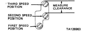
b. Speed control lever (15) a. Move into second (2) speed position.
b. Measure clearance between lever and top of slot as indicated.
Clearance must be 0.9-1.1 inch. Adjust as necessary
2-220
|


