| |
TM 10-3930-638-24&P
2-28. INSTRUMENT PANEL MAINTENANCE (cont)
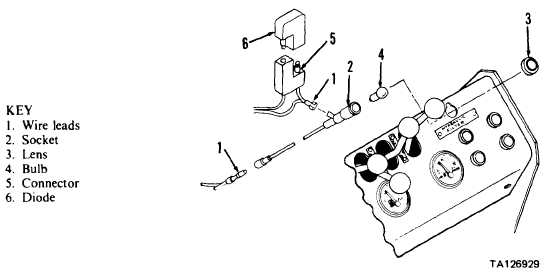
e. Warning Lights and Diodes.
This task covers: a. Removal
d. Testing
b. Cleaning
e. Installation
c. Inspection
INITIAL SETUP
TOOLS
None
MATERIALS/PARTS
Cleaning solvent P-D-680
Clean cloths
EQUIPMENT CONDITION
Paragraph
Condition Description
Engine off.
IGNITION switch in OFF position and
key removed.
2-53h
Noise baffle mat removed.
STEP
LOCATION
ITEM
ACTION
REMARKS
NOTE
All five warning light assemblies are identical except for legend
marked on lens (3). Isolation diode (6) for ALTERNATOR
warning light is located in engine compartment (see para 2-26).
Isolation diode (6) not used with OIL PRESSURE warning
light.
REMOVAL
1 Instrument panel, a. Wire leads (1)
Grasp and pull
From warning light terminals
far right side
b. Socket (2)
Push
Against instrument panel
c. Lens (3)
Rotate 1/4 turn
Support socket (2)
d. Socket (2)
Lower and
From instrument panel
remove
e. Bulb (4)
Remove
f. Isolation diode (6)
Grasp and pull
From connector (5)
2-137
|

