| |
TM 10-3930-638-24&P
2-19. TROUBLESHOOTING SYMPTOM INDEX (cont)
Para/Malfunction
CHARGING SYSTEM
Abnormal alternator light operation . . . . . . . . . . . . . . . . . . . . . . . . . . . . . . . . . . . . . . . . . . .
2-22/1
Alternator output low, unsteady, or zero . . . . . . . . . . . . . . . . . . . . . . . . . . . . . . . . . . . . . . .
2-22/2
HORN SYSTEM
Horn does not sound . . . . . . . . . . . . . . . . . . . . . . . . . . . . . . . . . . . . . . . . . . . . . . . . . . . . . . .
2-23/1
Back-up alarm does not sound.. . . . . . . . . . . . . . . . . . . . . . . . . . . . . . . . . . . . . . . . . . . . . . .
2-23/2
LIGHT SYSTEMS
Front floodlights inoperative.. . . . . . . . . . . . . . . . . . . . . . . . . . . . . . . . . . . . . . . . . . . . . . . .
2-24/1
Front black out light inoperative . . . . . . . . . . . . . . . . . . . . . . . . . . . . . . . . . . . . . . . . . . . . . .
2-24/2
Black out tail lights inoperative. . . . . . . . . . . . . . . . . . . . . . . . . . . . . . . . . . . . . . . . . . . . . . .
2-24/3
Service taillights inoperative. . . . . . . . . . . . . . . . . . . . . . . . . . . . . . . . . . . . . . . . . . . . . . . .
2-24/4
Black out stoplights inoperative . . . . . . . . . . . . . . . . . . . . . . . . . . . . . . . . . . . . . . . . . . . . . .
2-24/5
Service stoplights inoperative. . . . . . . . . . . . . . . . . . . . . . . . . . . . . . . . . . . . . . . . . . . . . . . .
2-24/6
Rear flood lights inoperative . . . . . . . . . . . . . . . . . . . . . . . . . . . . . . . . . . . . . . . . . . . . . . . . .
2-24/7
Gage lights inoperative . . . . . . . . . . . . . . . . . . . . . . . . . . . . . . . . . . . . . . . . . . . . . . . . . . . . . .
2-24/8
INSTRUMENT PANEL
Warning lights inoperative . . . . . . . . . . . . . . . . . . . . . . . . . . . . . . . . . . . . . . . . . . . . . . . . . . .
2-25/ 1
Warning lights, back-up alarm, and electric fuel pump inoperative . . . . . . . . . . . . . . . . . .
2-25/2
Page
2-103
2-104
2-105
2-106
2-107
2-107
2-108
2-109
2-109
2-110
2-110
2-111
2-112
2-113
2-20. BATTERY SYSTEM TROUBLESHOOTING
MALFUNCTION
TEST OR INSPECTION
CORRECTIVE ACTION
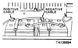
1. ALL ELECTRICAL SYSTEMS ARE WEAK
Step 1. Connect voltmeter leads to connectors of negative battery cable at battery post and starter
ground.
Note voltmeter indication while an assistant cranks engine.
a. If voltmeter indicates less than 0.5 Vdc, proceed to step 2.
b. If voltmeter indicates more than 0.5 Vdc, replace the negative battery cable
(para 2-33b)
Step 2. Connect voltmeter leads to connectors of positive battery cable at battery post and starter B terminal.
Note voltmeter indication while an assistant cranks engine.
a. If voltmeter indicates less than 0.5 Vdc,
proceed to step 3.
b. lf voltmeter indicates more than 0.5 Vdc,
replace the positive battery cable
(para 2-33 b).
2-99
|