 |
|||
|
|
|||
|
|
|||
| ||||||||||
|
|
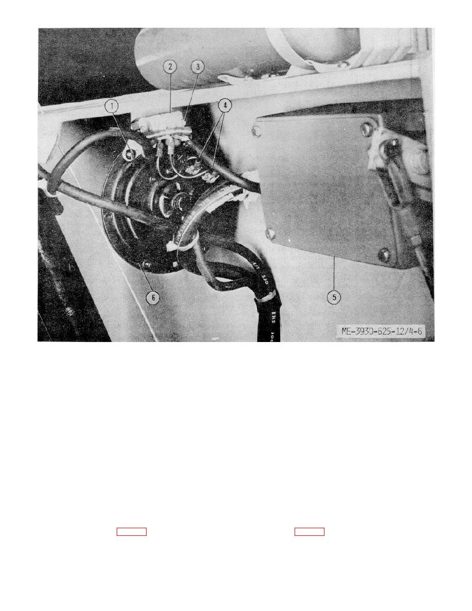
 1.
Screw
2.
Filter
3.
Screw
4.
Wire leads
5.
Accelerator switch
6.
Horn
Figure 4-6. Horn assembly and accelerator switch.
b. Cleaning, Inspection and Test.
(a) Remove the control box cover.
(b) Pull fuses (8) from holders at
(1) Wipe with a clean dry cloth.
(2) Inspect for frayed wires, worn or torn
bottom of control box.
(2) Cleaning and inspection.
insulation, corrosion, cracks, dents, loose or missing
hardware or other defects.
(a) Wipe with a clean, dry cloth.
(3) Test by pressing horn button.
(b) Inspect fuse and fuse holder for
(4) Replace a damaged or defective horn.
cracks, breaks, corrosion, loose connections, or other
(5) Replace defective wiring or filter.
defects.
c. Installation. Installation is the reverse of
(c) Replace a defective fuse.
removal.
(3) Installation. Installation is the reverse
4-21. Fuses
of removal.
a. Control Fuses.
b. Power Fuses.
(1) Removal (fig. 4-2).
4-13
|
|
Privacy Statement - Press Release - Copyright Information. - Contact Us |