 |
|||
|
|
|||
|
Page Title:
Section V. REPAIR OF WHEEL ASSEMBLIES |
|
||
| ||||||||||
|
|
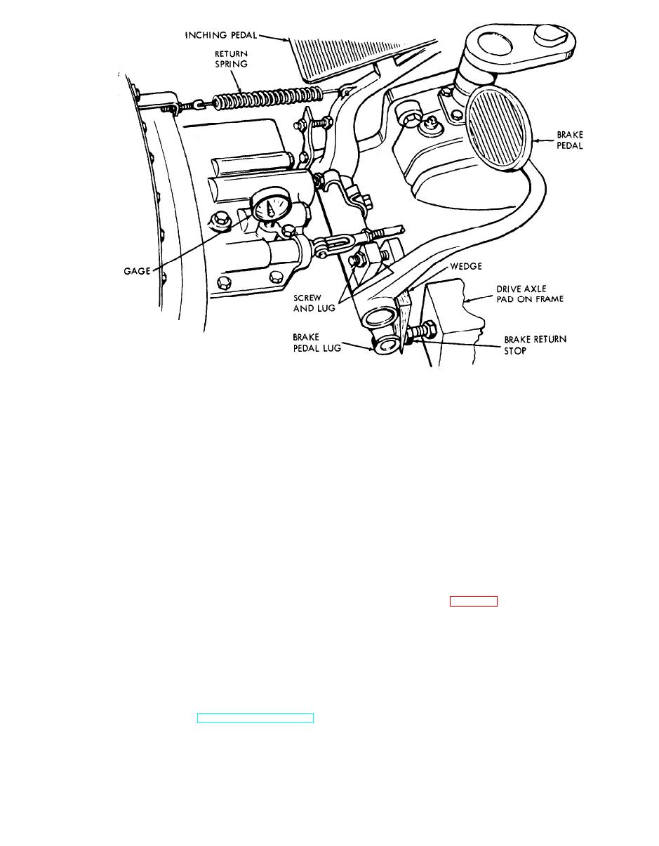
 ME 3930-624-34/4-22
Figure 4-22. Inching pedal hydraulic adjustment.
(f) Set the adjusting screw to contact the
forward and ensure that the pressure reading does
brake pedal lug and lock.
not increase. Shut down the engine.
(g) Operate the engine at high idle speed.
(h) Loosen the inching spring mounting
Remove the wedge and compress the inching pedal
capscrew and readjust the spring to a 3/32-1/8
spring to 3/32- 1/8 in. Pressure gage should
in. deflection. Tighten the capscrew. Check for free
indicate 100-160 psi. Pull the inching pedal
oscillation of the inching spring.
Section V. REPAIR OF WHEEL ASSEMBLIES
4-14. General
Note. Figure 4-23 is an illustration of the drive wheel.
The drive wheel assembly consists of a wheel, a tire,
The steer wheel is similar, with differences noted.
a bull gear and bearings. The bull gear is bolted
inside the wheel. Part of the space on the inside
(1) Remove capscrew (1), lockwasher (2), and
surface of the wheel serves as a brake drum. The
hub cap (3).
steer wheel assembly consists of a wheel, a tire and
(2) Remove cotter pin (4), bearing adjusting
nut (5), washer (6), and outer bearing (7).
4-15. Wheel Repair
a. Removal. Refer to TM 10-3930-624-12 for
the wheel removal procedure.
4-25
|
|
Privacy Statement - Press Release - Copyright Information. - Contact Us |