 |
|||
|
|
|||
|
Page Title:
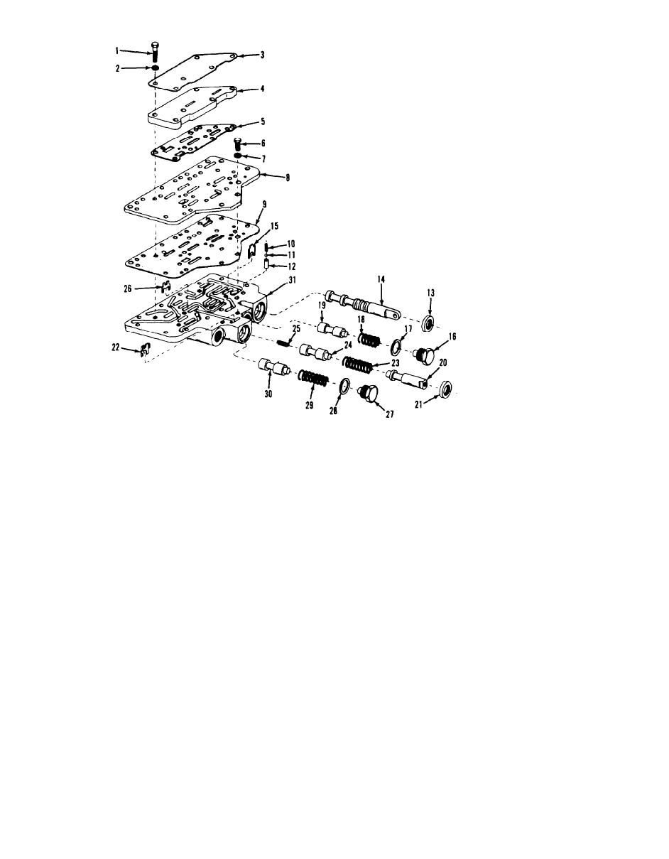
Figure 1-12. Control valve. exploded view. |
|
||
| ||||||||||
|
|
 ME 3930-624-34/4-12
17. Gasket
1. Bolt
18. Spring
2. Lockwasher
19. Dump valve
3. Cover
20. Plunger
4. PIate
21. Oil seal
5. Gasket
22. Stop
6. Capscrew
23. Spring
7. Lockwasher
24. Inching valve
8. Plate
25. Spring
9. Gasket
26. stop
10. Spring
27. Screw
11. Ball
28. Gasket
12. Sleeve
29. Spring
13. Oil seal
30. Regulator valve
14. Selector valve
51. Body
15. Stop
16. Screw
Figure 1-12. Control valve. exploded view.
(6) Remove the inching valve plunger (20), on
(2) Remove the capscrews (6). lockwasher (7),
seal (21). plunger stop (22). spring (23), inching
plate (8) and gasket (9).
valve (24), spring (25) and inching valve stop (26).
(3) Remove the spring (10). detent ball (11)
(7) Remove the spring retaining screw (27).
and sleeve (12).
gasket (28). spring (29) and regulator valve (30)
(4) Remove the oil seal (13) and selector valve
from the valve body (31).
(14). Remove the selector valve stop (15).
c. Cleaning. Inspection and Repair.
(5) Remove the spring retaining screw (16).
(1) Clean valve and components using suitable
gasket (17). spring (18) and dump valve (19).
4-10
|
|
Privacy Statement - Press Release - Copyright Information. - Contact Us |