 |
|||
|
|
|||
|
Page Title:
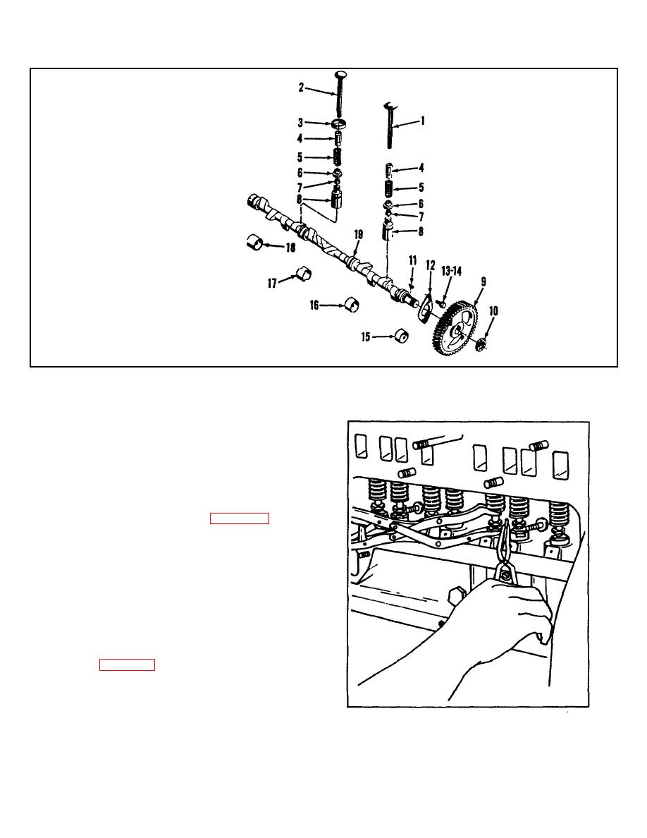
Figure 4-23. Engine Valve Train and Camshaft Group, Exploded View |
|
||
| ||||||||||
|
|
 TM 10-3930-623-34
1. Intake Valve
2. Exhaust Valve
3. Exhaust Valve Seat
Insert
4. Valve Guide
5. Valve Spring
6. Retainer
7. Retainer Lock
8. Valve Tappet
9. Camshaft Gear
10. Nut
11. Woodruff Key
12. Thrust Plate
13. Screw
14. Lock Washer
15. Camshaft Front Bushing
16. Camshaft Intermediate
Front Bushing
17. Camshaft Intermediate
Rear Bushing
18. Camshaft Rear Bushing
19. Camshaft
Figure 4-23. Engine Valve Train and Camshaft Group, Exploded View
5. Remove valve springs (5) and spring retainers
(6) from valve chamber.
6. Remove tappets (8) from cylinder block. Tag
tappets for replacement in holes from which they were
removed.
4-89. TIMING GEAR COVER ASSEMBLY.
4-90. REMOVAL. Remove screws and hollow dowels
securing the timing gear cover (2, figure 4-25) to the
cylinder block and remove cover assembly.
4-91. DISASSEMBLY.
NOTE
Examine both fan drive assembly and
governor control lever and shaft
assembly
to
determine
if
disassembly is required.
1. Remove three screws attaching fan
drive
assembly (52 figure 4-18) to timing gear cover.
2. Remove drive assembly (52) and roll pin.
3. Using suitable pullers remove drive gear and
pulley with keys. Remove shaft bearings.
Figure 4-24. Removing and Replacing Valve Retainer
Locks
4-28
|
|
Privacy Statement - Press Release - Copyright Information. - Contact Us |