 |
|||
|
|
|||
|
|
|||
| ||||||||||
|
|
 TM 10-3930-623-34
1-39. SPOTLIGHT ASSEMBLY. The sealed-beam
The ignition switch is
1-41.
IGNITION SWITCH.
spotlight is mounted on the left hand hoist upright. This
mounted on the instrument panel. Setting the ignition
light is operated by a toggle switch mounted on the
switch to ON position energizes the ignition system and
instrument housing.
instrument panel gages.
1-42. SENDING UNITS. Three sending units on the
truck actuate instruments on the instrument panel. The
fuel gage sending unit is mounted atop the fuel tank.
This unit consists of a float mounted on an arm attached
1-40.
COMBINATION TAIL AND STOP LIGHT
ASSEMBLY.
The tail and stop light assembly is
to a sliding contact.
The position of the arm is
mounted within a steel guard on tile upper rear of the
proportional to the quantity of fuel. The slider shorts out
engine compartment. The taillight operates when the
turns of a resistance winding to change the current in the
spotlight is turned on. The stop light is operated by the
gauge circuit proportional to the fuel level, which is
brake light switch when the foot brakes are used.
registered on the instrument.
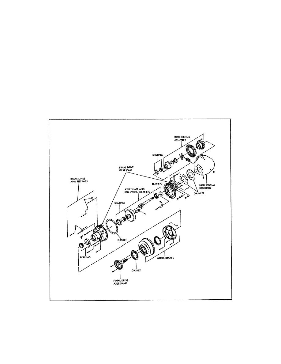
Figure 1-9. Drive Axle, Exploded View
1-10
|
|
Privacy Statement - Press Release - Copyright Information. - Contact Us |
